Time - Design Elements
Time - Vector clipart libraryThe vector stencils library Time is included in the Business and Finance solution from Illustration area of ConceptDraw Solution Park. Use it to quick draw illustrations, diagrams and infographics for your business and financial documents, presentations and websites. The clipart library Time includes 19 icons:
|
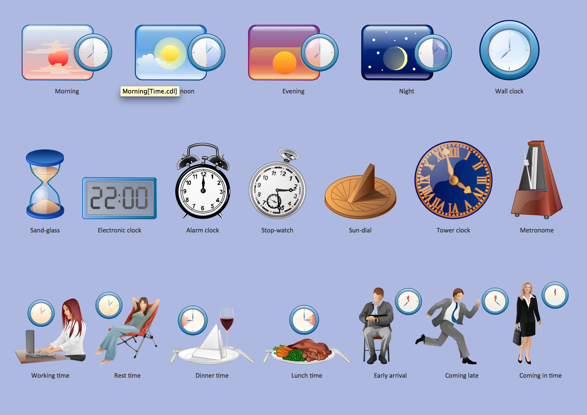
Pic.1 Time - Design Elements
See also Samples:
- Illustration - Aerospace and Transport
- Illustration - Artwork
- Illustration - Audio, video, media
- Illustration - Business and finance
- Illustration - Computers and communications
- Illustration - Manufacturing
- Illustration - Nature
- Illustration - People
- Illustration - Presentation clipart
- Illustration - Safety and security
- Science & Education — illustrations
TEN RELATED HOW TO's:
A cozy atmosphere is crucial for the success of any cafe or restaurant. To provide it, you should use restaurant floor plan software at the stage of design. If your establishment is located conveniently and has a harmonic atmosphere inside it, this is bound to be a success.
This sample Restaurant floor plan illustrates the possibilities of ConceptDraw solution for Cafe and Restaurant plans. It represents the location of the restaurant's main hall with its furnishing as well as a plan of kitchen and toilets. Generally, Cafe and Restaurant Plans solution has a big set vector images of tables, seats, lightening, etc. Using them you will be able to plan the restaurant of your desire with an incredible design and spirit.
Picture: Restaurant Floor Plan Software
Related Solution:
The Building Plans area of ConceptDraw Solution Park includes a set of solutions of Interior Design. The Interior Design solutions for ConceptDraw DIAGRAM allow you simply and quickly create the professional looking Building Plans that will help you to design, redesign your room, flat, home, office, cafe or any other building. Having the ready plan of the rooms you can easy rearrange the furniture, interior objects on the plan and see the future result at once.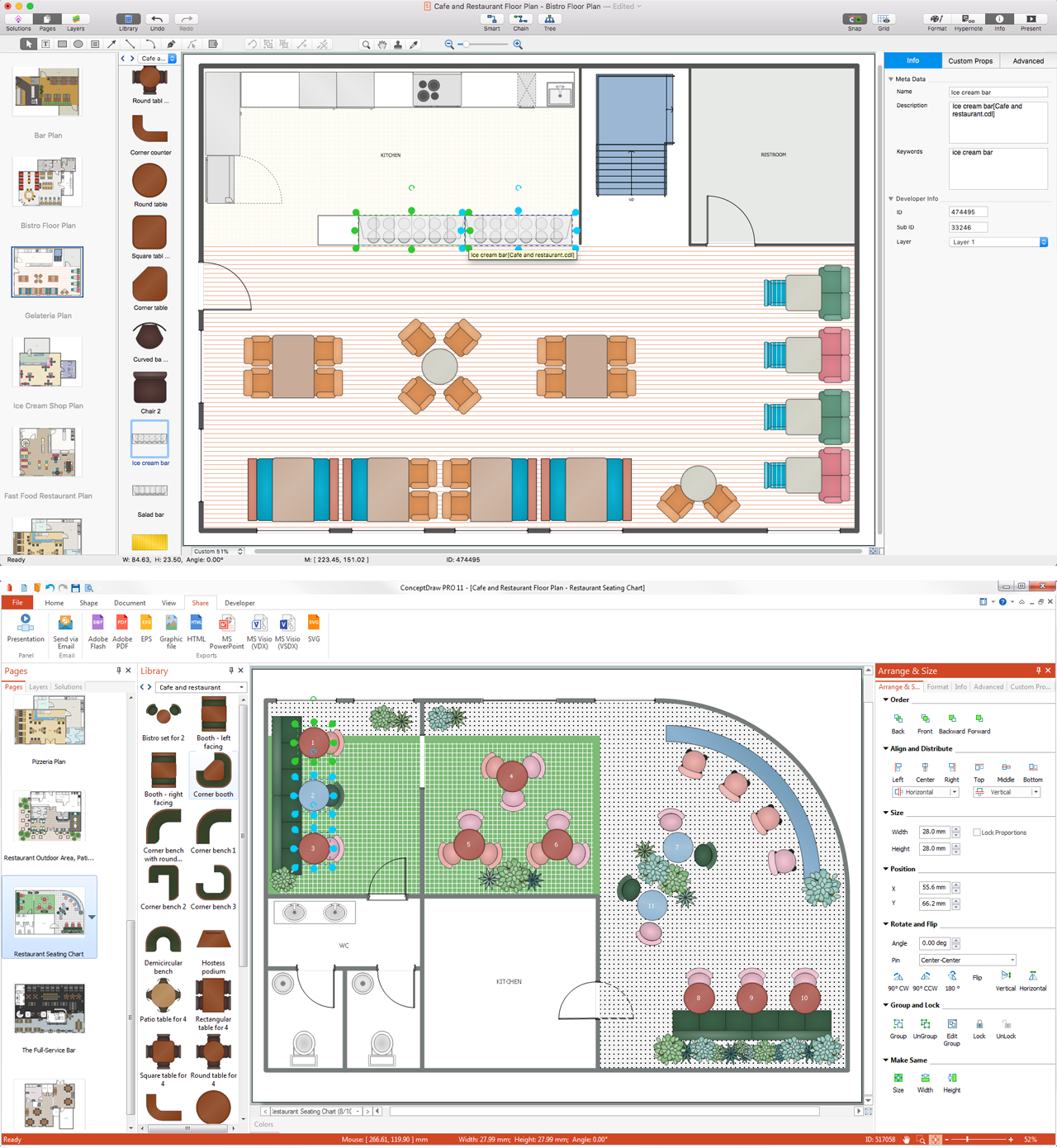
Picture: Interior Design Software. Building Plan Examples
Related Solution:
ConceptDraw - Perfect Network Diagramming Software with examples of Backbone Network Diagrams. ConceptDraw Network Diagram is ideal for network engineers and network designers who need to draw Backbone Network diagrams.
Picture: Network Diagram SoftwareBackbone Network
Chemical and Process Engineering solution contains variety predesigned process flow diagram elements relating to instrumentation, containers, piping and distribution necessary for chemical engineering, and can be used to map out chemical processes or easy creating various Chemical and Process Flow Diagrams in ConceptDraw DIAGRAM.
Picture: Process Flow Diagram Symbols
Related Solution:
ConceptDraw DIAGRAM software extended with Electric and Telecom Plans Solution is the best software for drawing the Telecom Wireless Plan of any complexity.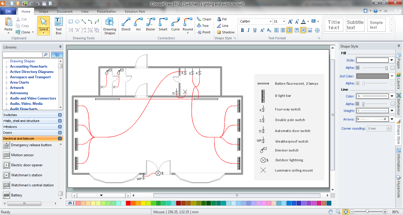
Picture: Telecom Wireless Plan
Related Solution:
Local area network connects computers and other network appliances within an area, such as office building or a campus. It can be difficult to provide such network without a predesigned plan. For these purposes you can use network diagram software, which helps you to create LAN network diagrams and office network diagrams quickly and effortless. This will speed up your work and you can save the diagram for the future network improvements.
The following diagram illustrates a network topology of the small office. LAN configuration has a star topology. The local network joins 8 computers among which are several desktop PCs, laptop, two iMacs and iBook. The end-point devices are divided into three groups. Each group is connected to its hub. There is a network printer and a modem, which are interconnected with other devices through a network server. Each computer on the LAN can access the server through a corresponding hub.
Picture: Network Diagram Software. LAN Network Diagrams. Physical Office Network Diagrams
Related Solution:
Data structure diagram (DSD) is intended for description of conceptual models of data (concepts and connections between them) in the graphic format for more obviousness. Data structure diagram includes entities description, connections between them and obligatory conditions and requirements which connect them. Create Data structure diagram with ConceptDraw DIAGRAM.
Picture: Data structure diagram with ConceptDraw DIAGRAM
ConceptDraw DIAGRAM diagramming and vector drawing software extended with Gym and Spa Area Plans solution from Building Plans area of ConceptDraw Solution Park contains a set of examples, templates and design elements libraries for drawing Gym Workout Plan, Gym Floor Plan, Gym Layout Plan, Spa Floor Plan, Fitness Plan, etc.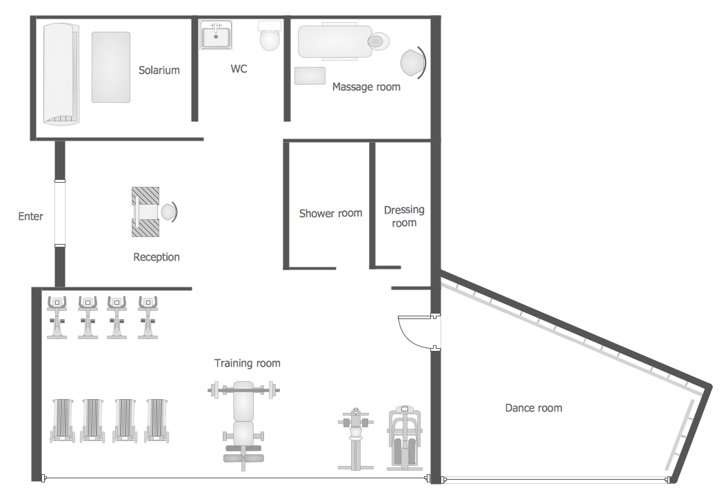
Picture: Gym Workout Plan
Related Solution:
The HR Management Software is an incredibly powerful tool for those who need to analyze or present human resource process flows in a visually effective manner.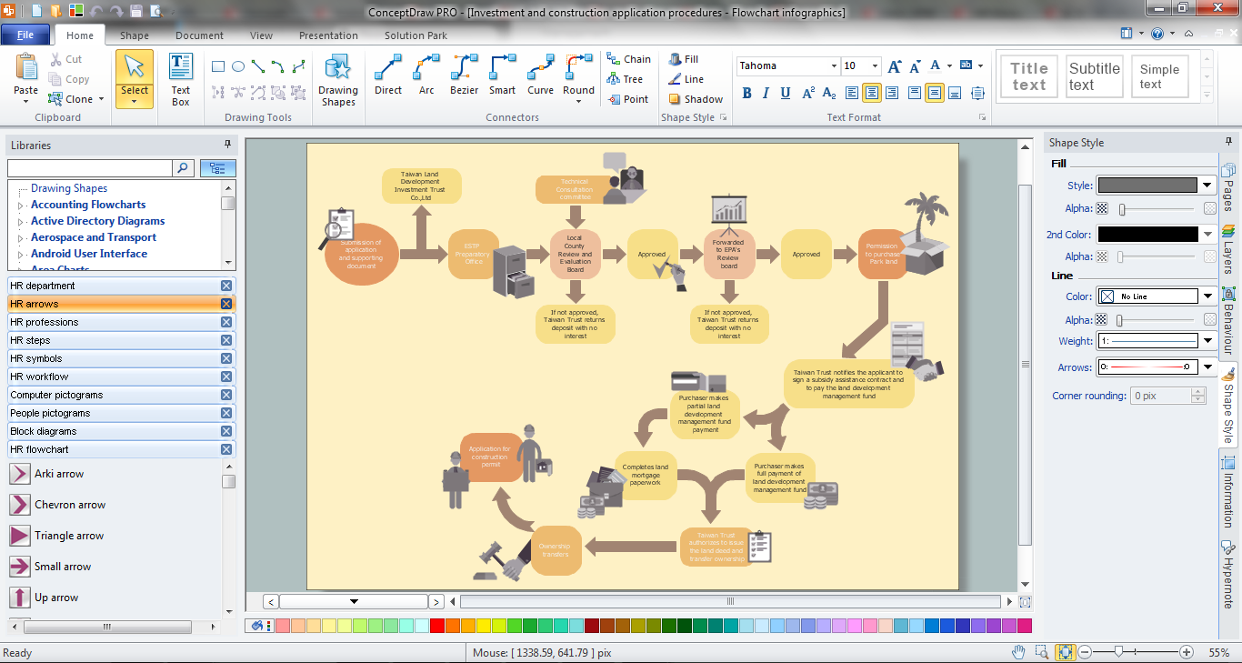
Picture: HR Management Software
Related Solution:
A detailed mind map about the various elements and stages of project management.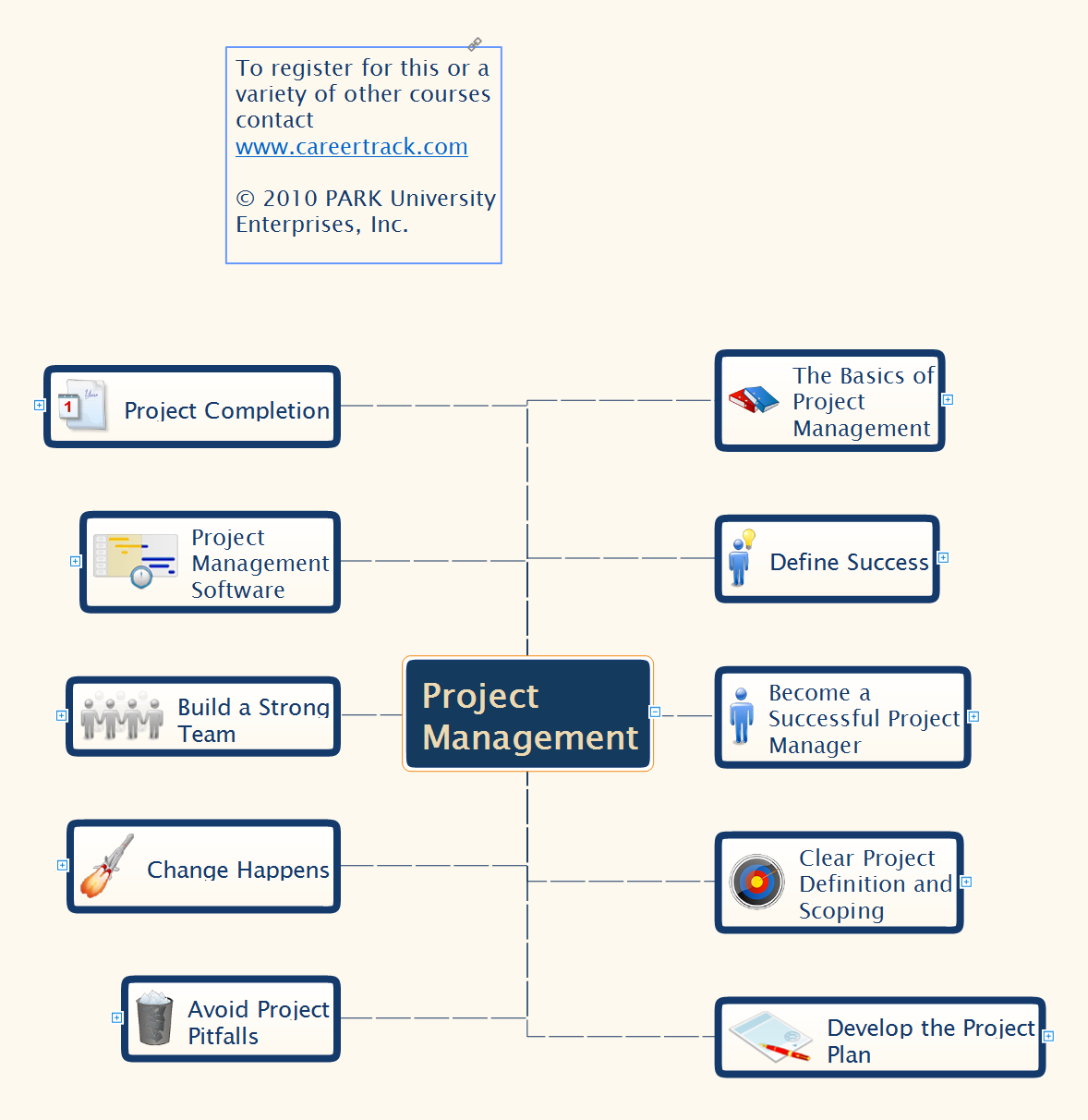
Picture: Project Management
Related Solution:
ConceptDraw
DIAGRAM 18