Cisco WAN.
Cisco icons, shapes, stencils and symbols
The ConceptDraw vector stencils library "Cisco WAN" contains 15 equipment symbols for drawing the computer wide area network diagrams using the ConceptDraw DIAGRAM diagramming and vector drawing software:
- CSU/DSU
- WAN
- MUX
- PBX/switch
- Hub
- Hub, Blue
- NAT
- Network cloud, dark
- Network cloud, gold
- Network cloud, white
- Network cloud, standard color
- Distributed director
- Local director
- PBX
- DPT

Sample 1. Design Elements — Cisco WAN (macintosh, windows)
for Network Diagrams.
The example "Design elements - Cisco WAN" is included in the Cisco Network Diagrams solution from the Computer and Networks area of ConceptDraw Solution Park.
Icons, shapes, stencils, symbols and design elements for Cisco Network Diagrams:
TEN RELATED HOW TO's:
ConceptDraw DIAGRAM is perfect for software designers and software developers who need to draw Network Active Directory Diagrams.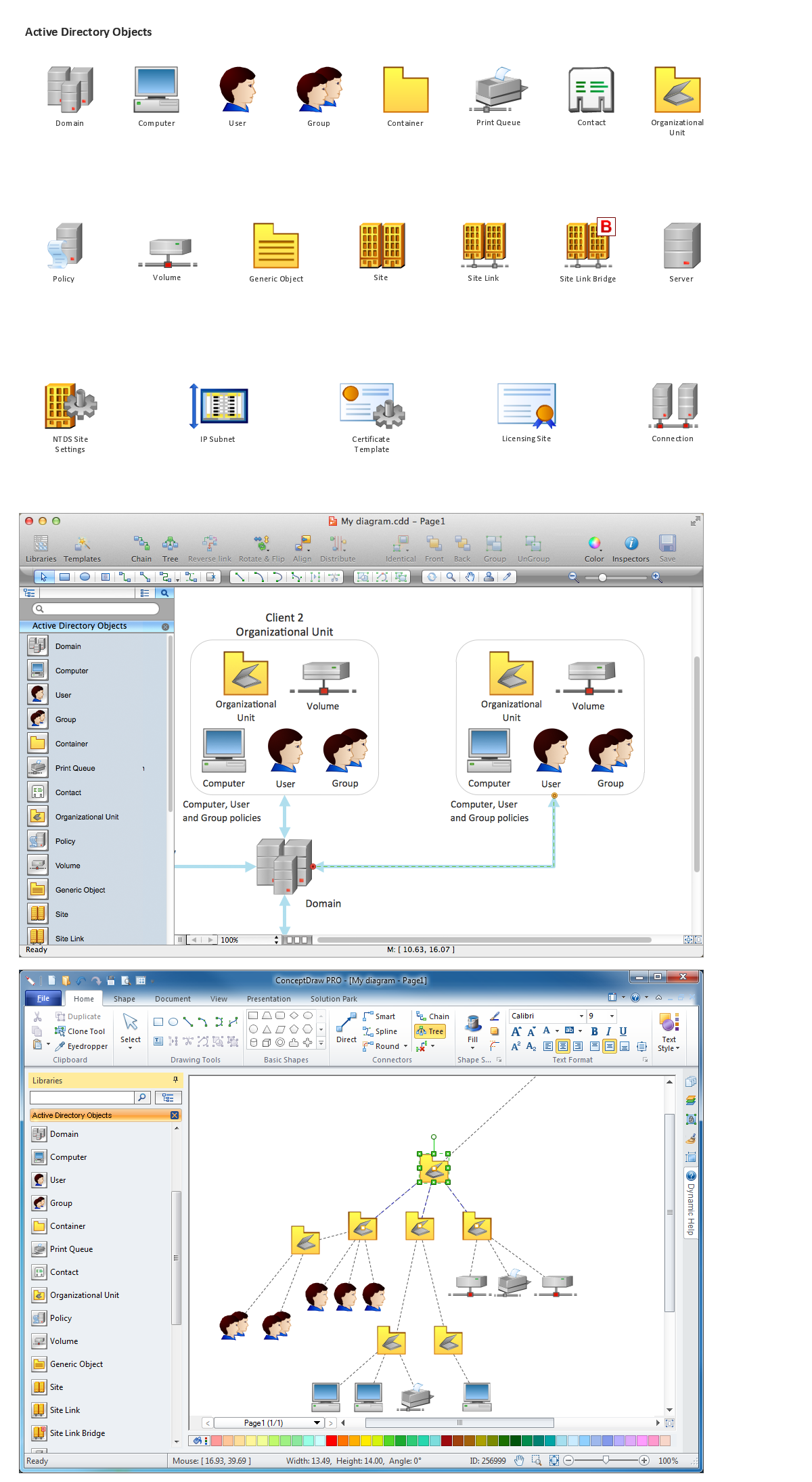
Picture: Network Diagramming Software for Network Active Directory Diagrams
Computer and Networks solution provides examples, templates and vector stencils library with symbols of local area network (LAN) and wireless LAN (WLAN) equipment.
This example of computer network topology diagram shows home WLAN equipment and their connection to the Internet.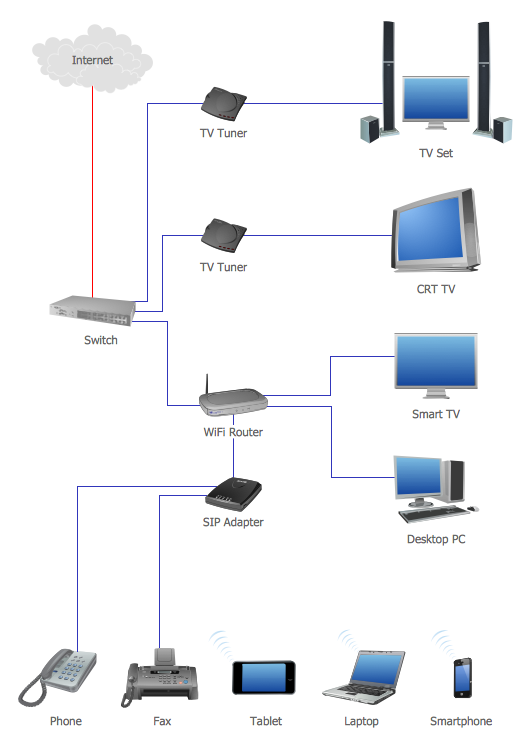
Picture: Network Topology Graphical Examples
Related Solution:
What is Cloud Computing? The Cloud computing is a widely used and highly demanded utility in the modern world thanks to its high computing power, performance, scalability and accessibility, and at the same time low cost of services. The ConceptDraw DIAGRAM diagramming and vector drawing software provides an easy and effective Cloud Computing Diagrams solution from the Computers and Network area of ConceptDraw Solution Park for making professional looking Cloud Computing and Cloud Computing Architecture Diagrams.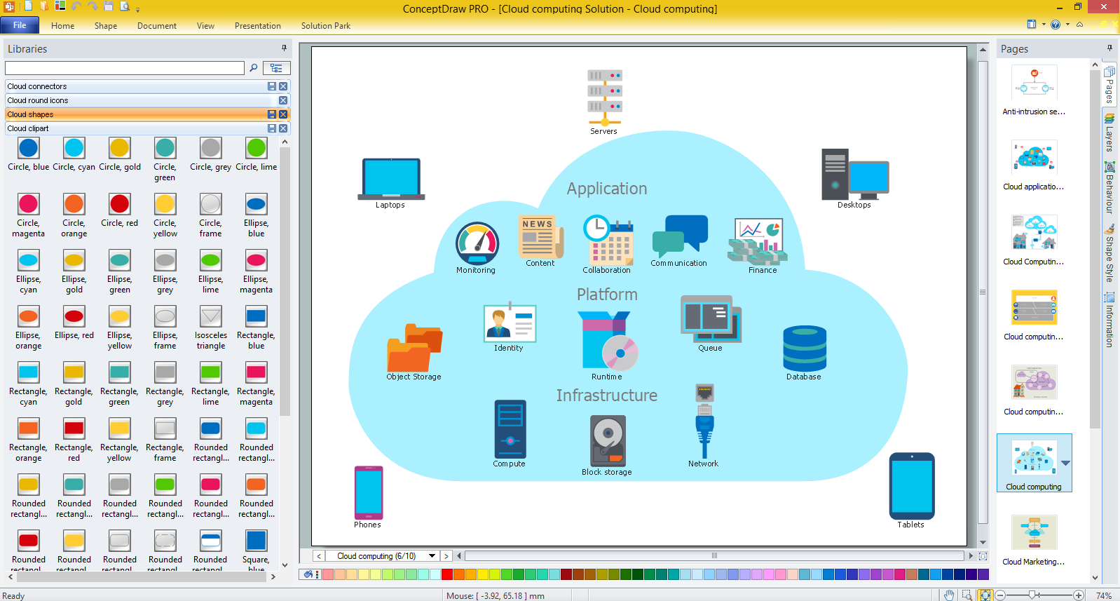
Picture: What is Cloud Computing
Related Solution:
OSPF is an interior gateway protocol (IGP), it is widely used in large enterprise networks. OSPF routes the IP packets within a single routing domain. It gathers the information about the link state from the routers and makes the network topology map.
This example was created in ConceptDraw DIAGRAM using the Computer and Networks Area of ConceptDraw Solution Park and shows the OSPF diagram.
Picture: OSPF Network. Computer and Network Examples
Related Solution:
ConceptDraw DIAGRAM is a flowchart design software. There are large collections of professional flowchart symbols for process flow diagrams, standard flowchart symbols and colored basic flowchart symbols. Built-in examples and video lessons allow users to get started immediately and do drawing of virtually any type of flowchart or process flow diagrams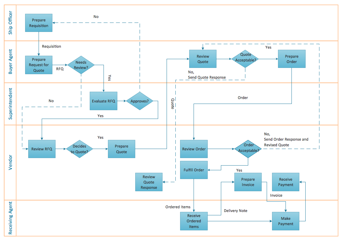
Picture: Flow Chart Creator
Related Solution:
UML state machine's goal is to overcome the main limitations of traditional finite-state machines while retaining their main benefits.
ConceptDraw has 393 vector stencils in the 13 libraries that helps you to start using software for designing your own UML Diagrams. You can use the appropriate stencils of UML notation from UML State Machine library.
Picture: UML State Machine Diagram.Design Elements
Related Solution:
You need to draw a Functional Flow Block Diagram? You are an artist? Now it doesn't matter. With Block Diagrams solution from the Diagrams area for ConceptDraw Solution Park you don't need more to be an artist to design the Functional Flow Block Diagram of any complexity.
Picture: Functional Flow Block Diagram
Related Solution:
This sample was created in ConceptDraw DIAGRAM diagramming and vector drawing software using the UML Deployment Diagram library of the Rapid UML Solution from the Software Development area of ConceptDraw Solution Park.
This sample shows the work of the ATM (Automated Teller Machine) banking system that is used for service and performing of the banking transactions using ATMs. System engineers can use comprehensive UML diagrams solution.
Picture: UML Deployment Diagram Example - ATM SystemUML diagrams
Related Solution:
Video tutorials on ConceptDraw products. Try it today!
Picture: Creating a default presentation in ConceptDraw MINDMAP for Macintosh
Drawing ISG Network Diagram using ConceptDraw DIAGRAM stencils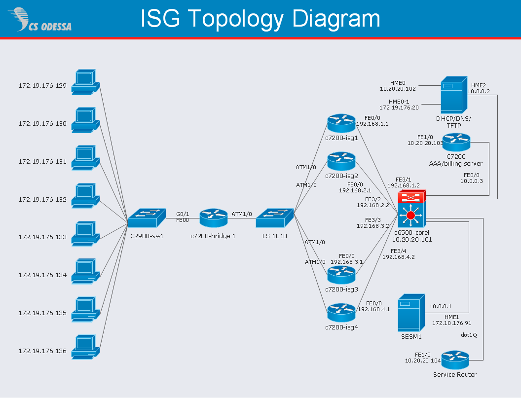
Picture: Network Diagram SoftwareISG Network Diagram
ConceptDraw
DIAGRAM 18