Cisco Products Additional.
Cisco icons, shapes, stencils and symbols
The ConceptDraw vector stencils library "Cisco Products Additional" contains 141 equipment symbols for drawing the computer network diagrams using the ConceptDraw DIAGRAM diagramming and vector drawing software:
- Protocol translator
- CiscoWorks workstation
- Access server (communications server)
- Workgroup director
- Network management appliance
- Storage Solution Engine (SSE)
- Software based router on file / application server
- Cisco MeetingPlace Express
- PC router card
- Transpath
- Bridge
- IOS SLB
- 100BaseT hub
- uBR910
- CDDI-FDDI
- PC adapter card
- VIP
- CSM-S
- Terminal server
- Route/switch processor with Si
- Route/switch processor
- PXF
- AVS (Application Velicity System)
- Content engine (cache director)
- Cisco file engine
- Management Engine (ME 1100)
- PC with router-based software
- PC with software
- ASIC processor
- General processor
- Switch processor
- Cisco 5500 family
- Multi-switch device
- IP transport concentrator
- ITP
- Cisco CA
- Voice Gateway
- BBSM
- ATA
- SIP Proxy Server
- MicroWeb Server
- NetRanger
- Cisco 6920 RateMux
- NetSonar
- Cisco 1000
- IP
- System controller
- ACE
- Voice-enabled access server
- Voice-enabled communications server
- Directory server
- Cisco 4310 End Office System
- ADM
- FireWall Service Module (FWSM)
- Cisco Unity Express
- Cisco Unity Server
- Centri firewall
- Cisco Security Manager
- Data switch processor (AKA data center switch)
- Cisco MP
- IOS firewall
- PIX firewall right
- PIX firewall left
- Cisco CallManager
- Cisco 6700 Series
- MGX 8240
- MGX 8220
- MGX 8260
- DSLAM
- Cisco 6732 Access Server
- Cisco 6701
- H.323
- Access gateway
- ICS 7750
- VPN concentrator
- SSL terminator
- CDM (Content Distribution Manager)
- Cisco 15200
- Cisco 15800
- Content Service Module
- Content Transformation Engine (CTE)
- Cisco VN 2900
- Cisco VN 5900
- Cisco VN 5902
- Cisco Unified Presence Server
- ICM
- PC Card
- Access point
- Dual mode access point
- Ether client
- Tablet
- Wireless transport
- Wireless bridge
- Lightweight single radio access point
- Lightweight double radio access point
- WLAN controller
- Wi-Fi tag
- Wireless location appliance
- Wireless connectivity
- WiSM
- Mesh AP
- SC2200 Signaling Controller
- Virtual Switch Controller (VSC3000)
- VS C3000 or SC2200 host
- BTS 10200 Softswitch
- Detector
- IP/TV content manager
- IP / TV broadcast server
- Universal gateway
- Generic softswitch
- Generic softswitch, blue
- Guard
- Mobile access router
- Cisco Carrier Routing System
- FC storage
- Intelli Switch Stack
- Service control
- UPC (Unified Personal Communicator)
- PMC
- IP communicator
- Streamer
- Vault
- DWDM filter
- DWDM ring
- DWDM network line
- Streamer (half-full)
- Vault (half-full)
- Data center switch, reversed
- Scanner
- 10GE/FCoE
- car
- CUBE
- Director-class fibre channel director
- Fibre channel disk subsystem
- Fibre channel fabric switch
- Generic gateway
- Handheld
- Internet streamer
- jbod
- MAS gateway
- Mesh AP
- Mobile streamer


Sample 1. Design Elements — Cisco Products Additional (macintosh, windows)
for Network Diagrams.
The example "Design elements - Cisco Products Additional" is included in the Cisco Network Diagrams solution from the Computer and Networks area of ConceptDraw Solution Park.

Example 2. Cisco Solution
Icons, shapes, stencils, symbols and design elements for Cisco Network Diagrams:
TEN RELATED HOW TO's:
Samples, templates and libraries contain vector clip art for drawing the Aerospace Illustrations.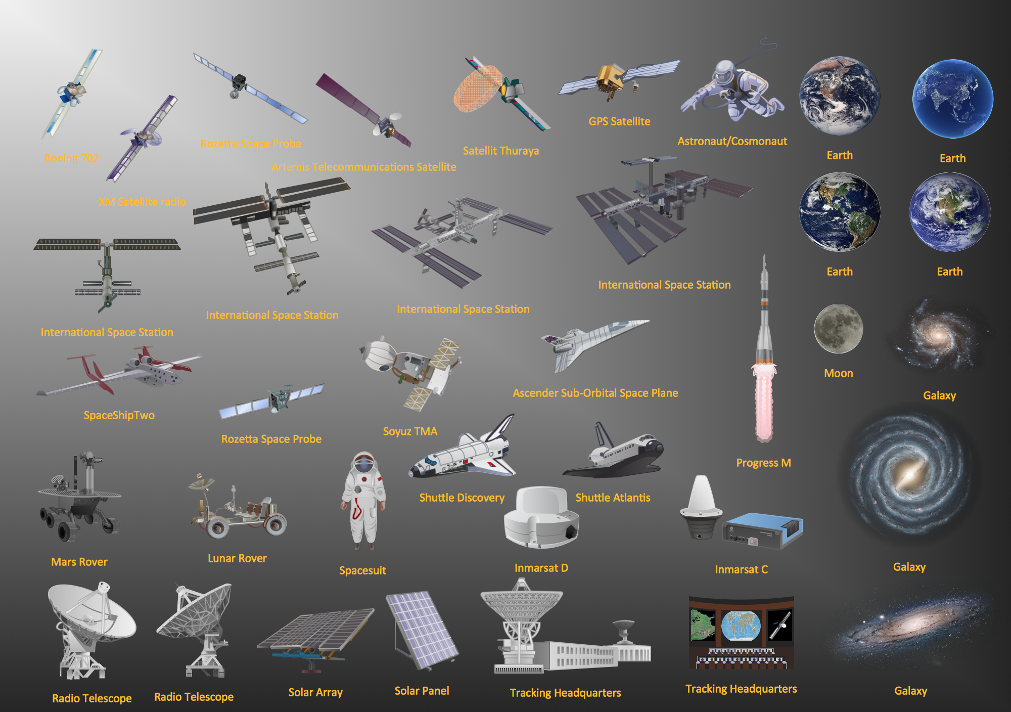
Picture: Aerospace - Design Elements
Related Solution:
Diagramming is an astonishing way to visualize business processes. The list of the most common business process flowchart symbols is quite long starting from basic flowcharts, continuing with SIPOC diagrams. Business process modeling was never easier than now, with special ConceptDraw Business Process Mapping solution.
To carry out all professional standard requirements for business processes mapping, it is necessarily to follow the special graphical notations. ConceptDraw Business Process Mapping solution offers an exhaustive suite of tools to aid business process mapping. There are three vector libraries SIPOC Diagrams, Business Process Flowcharts, and Swim Lanes that contains totally more than 50 symbols of standard BPM notations. This is all that professionals need to effectively evaluate and manage quality in business processes.
Picture: Business Process Flowchart Symbols
Related Solution:
ConceptDraw DIAGRAM diagramming and vector drawing software enhanced with Electrical Engineering Solution from the Industrial Engineering Area of ConceptDraw Solution Park offers you powerful tools and libraries with incredibly large quantity of predesigned electrical symbols as electrical schematic symbols for easy designing professional looking Electrical Schematics.
Picture: Electrical Symbols, Electrical Schematic Symbols
Related Solution:
ConceptDraw DIAGRAM diagramming and vector drawing software provides the Telecommunication Network Diagrams Solution from the Computer and Networks Area for quick and easy drawing the Telecommunications Networks.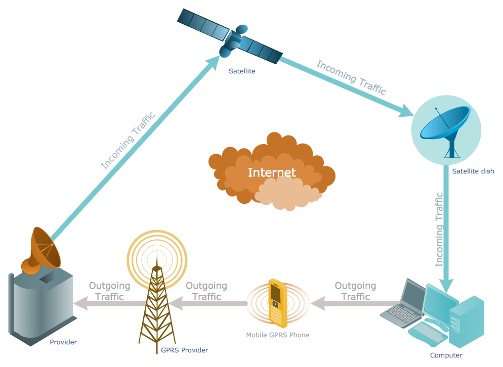
Picture: Telecommunications Networks
Related Solution:
Cabinet is a necessary room in the house. It is very important that the cabinet was comfortable and convenient with elaborated design that dispose to the maximize productive work. The cabinet design is a reflection of the personality, habits and character traits of its owner.
Floor Plans Solution provides templates, samples and wide collection of pre-designed vector stencils that allow you to create the cabinet design plans of any complexity quick, easy and effective.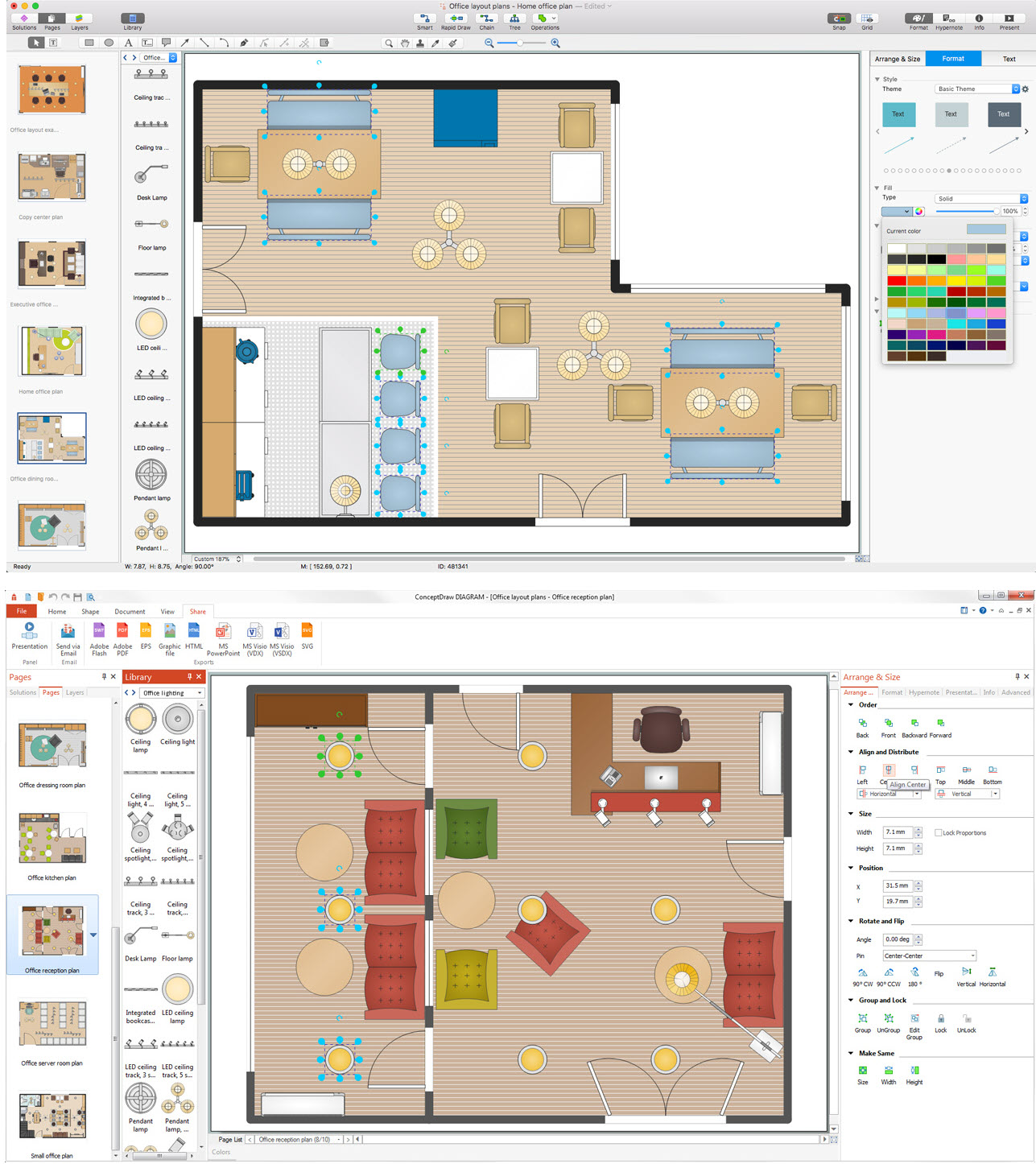
Picture: Cabinet Design Software
Related Solution:
When thinking about data visualization, one of the first tools that comes to mind is a flowchart design. You can find flowchart symbols, shapes, stencils and icons easily on the Internet, but it might take time to systematize this information. Nevertheless, once you start flowcharting, you’ll love its simplicity and efficiency.
This diagram consists from standard flowchart symbols, approved by ANSI (American National Standard Institute) for drawing flowcharts. A flowchart is a diagram that represents a step-by-step algorithm of any process, displaying the process stages as boxes that are connected with arrows. Flowchart design makes it clear and readable.
Flowchart designed using ConceptDraw DIAGRAM flowchart software allows to make attractive and clear process presentation, it makes interpretation of the business process flow fresh and versatile. Great flowchart design view is a big advantage over the diagram created manually on a paper.
Picture: Flowchart Design: Principles, Layout, Symbols and Best Practices
Related Solution:
Compare flowchart software by type, features, and workflow fit. Learn the difference between desktop and online tools and choose the right solution for documentation or collaboration.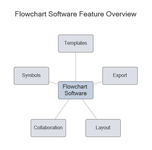
Picture: Flowchart Software: Tools for Process and Workflow Diagramming
Related Solution:
ConceptDraw DIAGRAM extended with IDEF0 Diagrams solution from the Software Development area of ConceptDraw Solution Park is a powerful diagramming and vector drawing IDEF0 software. All IDEF0 diagrams created in ConceptDraw DIAGRAM are vector graphic documents and can be reviewed, modified and converted to MS Visio XML format. To obtain the IDEF0 Visio documents from ConceptDraw DIAGRAM documents use the wide export possibilities of ConceptDraw DIAGRAM.
Picture: IDEF0 Visio
Related Solution:
A network diagram is used to depict the topology of a computer network or, talking more broadly, any telecommunications network in general. In order for a computer network diagram to be understandable, clearly identifiable icons must be used for each network appliance. Cisco network templates, also called Network Topology Icons, is a brand of symbols developed and used by Cisco. Since Cisco Systems is the largest networking company in the world, it's list of networking symbols is widely recognized and exhaustive.
The diagram of the ISG network topology diagram illustrates the Cisco Intelligent Services Gateway. Since Cicso company offers service providers a possibility to provide control of state and resources in a broadband network, network architects and engineers need some facilities to create ISG topology diagrams.This Cisco ISG network diagram was created in ConceptDraw DIAGRAM using its solution for Cisco network diagrams. The vector library of this solution comprises over 500 icons of Cisco hardware and accessories. They can be used to design LAN, WAN, ISG and other Cisco equipped network diagrams.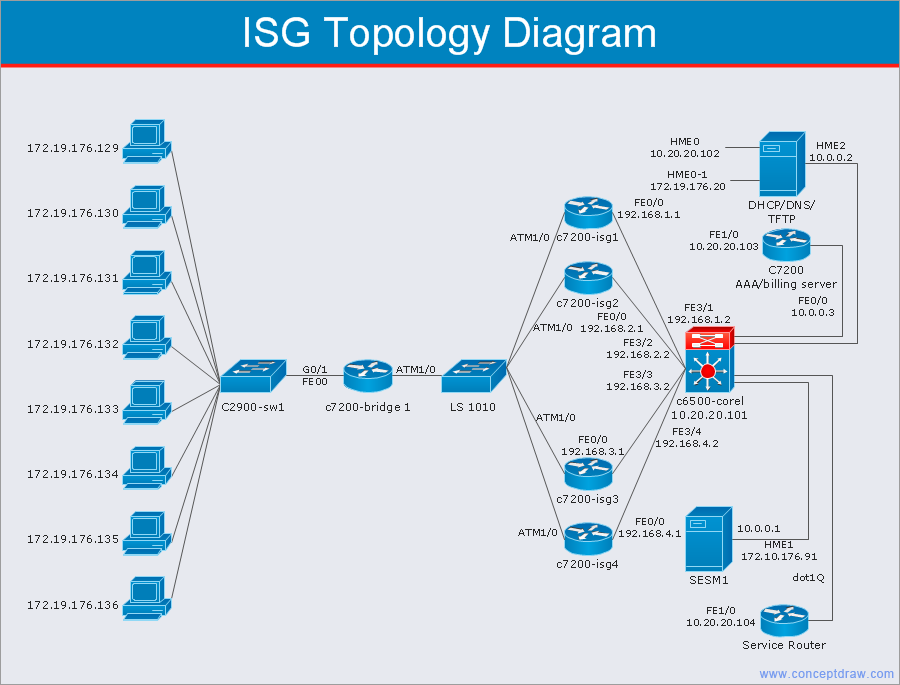
Picture: Cisco Network Templates
Related Solution:
The Cisco Network Diagrams solution from the Computer and Networks area of ConceptDraw Solution Park provides a wide collection of predesigned templates and samples that help you to create the Cisco Network Diagrams in one moment.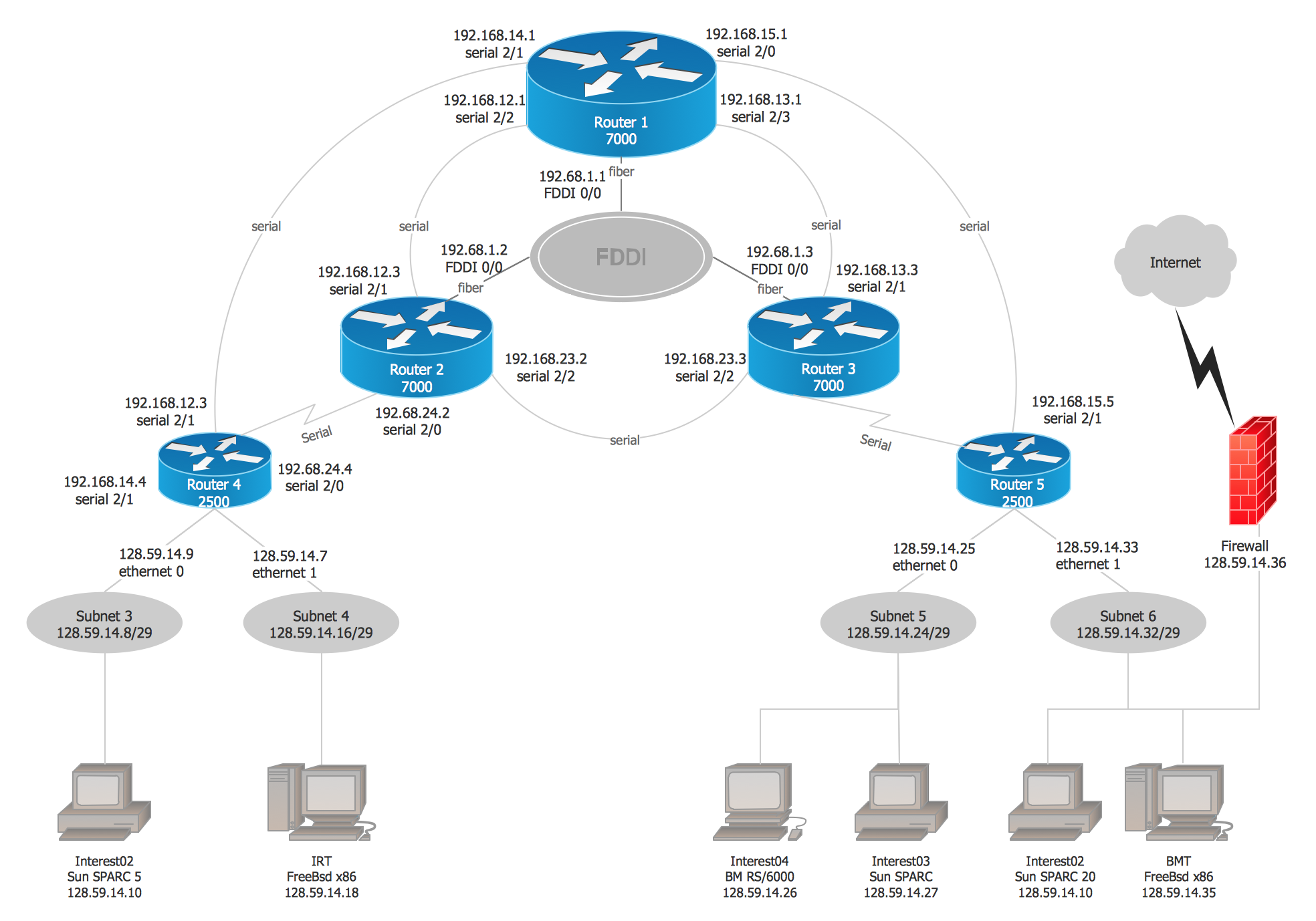
Picture: Cisco Network Examples and Templates
Related Solution:
ConceptDraw
DIAGRAM 18