- Electric and Telecom Plans Free
- Fire and Emergency Plans Free
- Floor Plans Free
- Plant Layout Plans Free
- School and Training Plans Free
- Seating Plans Free
- Security and Access Plans Free
- Site Plans Free
- Sport Field Plans Free
- Business Process Diagrams Free
- Business Process Mapping Free
- Classic Business Process Modeling Free
- Cross-Functional Flowcharts Free
- Event-driven Process Chain Diagrams Free
- IDEF Business Process Diagrams Free
- Logistics Flow Charts Free
- Workflow Diagrams Free
- ConceptDraw Dashboard for Facebook Free
- Mind Map Exchange Free
- MindTweet Free
- Note Exchange Free
- Project Exchange Free
- Social Media Response Free
- Active Directory Diagrams Free
- AWS Architecture Diagrams Free
- Azure Architecture Free
- Cisco Network Diagrams Free
- Cisco Networking Free
- Cloud Computing Diagrams Free
- Computer Network Diagrams Free
- Google Cloud Platform Free
- Interactive Voice Response Diagrams Free
- Network Layout Floor Plans Free
- Network Security Diagrams Free
- Rack Diagrams Free
- Telecommunication Network Diagrams Free
- Vehicular Networking Free
- Wireless Networks Free
- Comparison Dashboard Free
- Composition Dashboard Free
- Correlation Dashboard Free
- Frequency Distribution Dashboard Free
- Meter Dashboard Free
- Spatial Dashboard Free
- Status Dashboard Free
- Time Series Dashboard Free
- Basic Circle-Spoke Diagrams Free
- Basic Circular Arrows Diagrams Free
- Basic Venn Diagrams Free
- Block Diagrams Free
- Concept Maps Free
- Family Tree Free
- Flowcharts Free
- Basic Area Charts Free
- Basic Bar Graphs Free
- Basic Divided Bar Diagrams Free
- Basic Histograms Free
- Basic Line Graphs Free
- Basic Picture Graphs Free
- Basic Pie Charts Free
- Basic Scatter Diagrams Free
- Aerospace and Transport Free
- Artwork Free
- Audio, Video, Media Free
- Business and Finance Free
- Computers and Communications Free
- Holiday Free
- Manufacturing and Maintenance Free
- Nature Free
- People Free
- Presentation Clipart Free
- Safety and Security Free
- Analog Electronics Free
- Audio and Video Connectors Free
- Basic Circuit Diagrams Free
- Chemical and Process Engineering Free
- Digital Electronics Free
- Electrical Engineering Free
- Electron Tube Circuits Free
- Electronic Block Diagrams Free
- Fault Tree Analysis Diagrams Free
- GHS Hazard Pictograms Free
- Home Automation and Wiring Free
- Mechanical Engineering Free
- One-line Diagrams Free
- Power Сircuits Free
- Specification and Description Language (SDL) Free
- Telecom and AV Circuits Free
- Transport Hazard Pictograms Free
- Data-driven Infographics Free
- Pictorial Infographics Free
- Spatial Infographics Free
- Typography Infographics Free
- Calendars Free
- Decision Making Free
- Enterprise Architecture Diagrams Free
- Fishbone Diagrams Free
- Organizational Charts Free
- Plan-Do-Check-Act (PDCA) Free
- Seven Management and Planning Tools Free
- SWOT and TOWS Matrix Diagrams Free
- Timeline Diagrams Free
- Australia Map Free
- Continent Maps Free
- Directional Maps Free
- Germany Map Free
- Metro Map Free
- UK Map Free
- USA Maps Free
- Customer Journey Mapping Free
- Marketing Diagrams Free
- Matrices Free
- Pyramid Diagrams Free
- Sales Dashboard Free
- Sales Flowcharts Free
- Target and Circular Diagrams Free
- Cash Flow Reports Free
- Current Activities Reports Free
- Custom Excel Report Free
- Knowledge Reports Free
- MINDMAP Reports Free
- Overview Reports Free
- PM Agile Free
- PM Dashboards Free
- PM Docs Free
- PM Easy Free
- PM Meetings Free
- PM Planning Free
- PM Presentations Free
- PM Response Free
- Resource Usage Reports Free
- Visual Reports Free
- House of Quality Free
- Quality Mind Map Free
- Total Quality Management TQM Diagrams Free
- Value Stream Mapping Free
- Astronomy Free
- Biology Free
- Chemistry Free
- Language Learning Free
- Mathematics Free
- Physics Free
- Piano Sheet Music Free
- Android User Interface Free
- Class Hierarchy Tree Free
- Data Flow Diagrams (DFD) Free
- DOM Tree Free
- Entity-Relationship Diagram (ERD) Free
- EXPRESS-G data Modeling Diagram Free
- IDEF0 Diagrams Free
- iPhone User Interface Free
- Jackson Structured Programming (JSP) Diagrams Free
- macOS User Interface Free
- Object-Role Modeling (ORM) Diagrams Free
- Rapid UML Free
- SYSML Free
- Website Wireframe Free
- Windows 10 User Interface Free
Electron Tube Circuits
An electron tube (also known as a vacuum tube) is often used to amplify weak currents or act as a one-way valve for electric current. Electron tubes perform controlling the flow of electrons in a circuit by means of another flow of electrons. Thus, a comparatively small electric signal controls a comparatively high electric current. This is the difference between the concept of "electronic" and "electrical", which has more about how the flow of electrons is regulated by Ohm's law and the physical properties of wires and components.
Electron tubes are used as switches, amplifiers, or display screens (CRT). Used as on/off switches, vacuum tubes allowed the first computers to perform digital computations. Besides, electron tubes are still used in high-end stereo components. Electron tube circuit diagrams are indispensable in the design, construction, and maintenance of electronic equipment.
There are many types of electron tubes, each with its own applications. Slow-wave devices are intended to create conditions when an electromagnetic wave can be most powerful for interaction with a moving electron beam. Slow-wave tubes include diodes, also photodiodes, gamma-ray detector tubes, triodes, tetrodes, pentodes, cathode-ray tubes (CRT), inductive output amplifiers (IOA), e.t.c. Typically, such tubular metal structures are located inside a single glass shell.
There is also a type of electron tube known as fast-wave devices, and these are characterized by the phase velocity of the resonant wave having speeds greater than the speed of light. They operate at the high microwave frequency bands up to visible light. Specifically, these are the: gyrotron, also known as the cyclotron resonance maser., and free-electron laser (FEL).
Electron Tube Circuits solution extends the functionality of ConceptDraw DIAGRAM software with a large variety of internationally standardized icons and symbols for a schematic representation of various electronic tubes and their elements. The set of libraries is supplemented with electronic circuit diagram symbols including, inductors, amplifiers, relays, and many more. The icons for electronic equipment, circuit instrumentation, slow-wave, and fast-wave components, digital electronics symbols are also provided. Use them to illustrate the electronic circuit of any kind and complexity in minutes. A set of custom-designed electronic valve schematics illustrates the solution's capabilities for designing circuit diagrams, electronic circuits, and more.
Electron Tube Circuits solution is designed to assist electronic engineers, technicians, and many more electricity-related specialists in designing electronic circuits, devices, integrated circuits, and their systems.
-
What I need to get started -
Solution Requirements - This solution requires the following products to be installed:
-
Support for this Solution -
Helpdesk
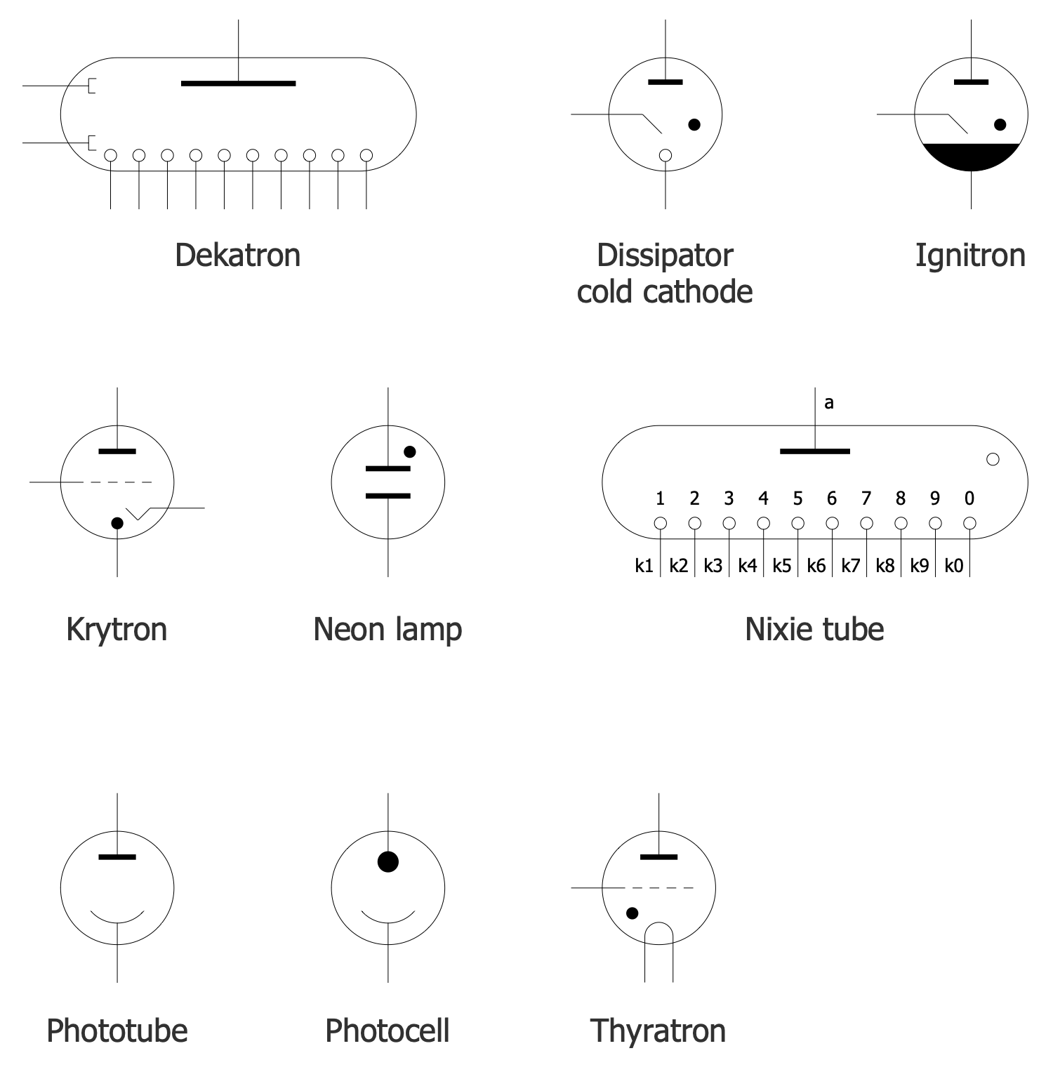
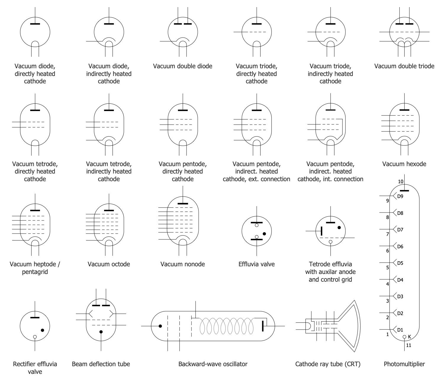
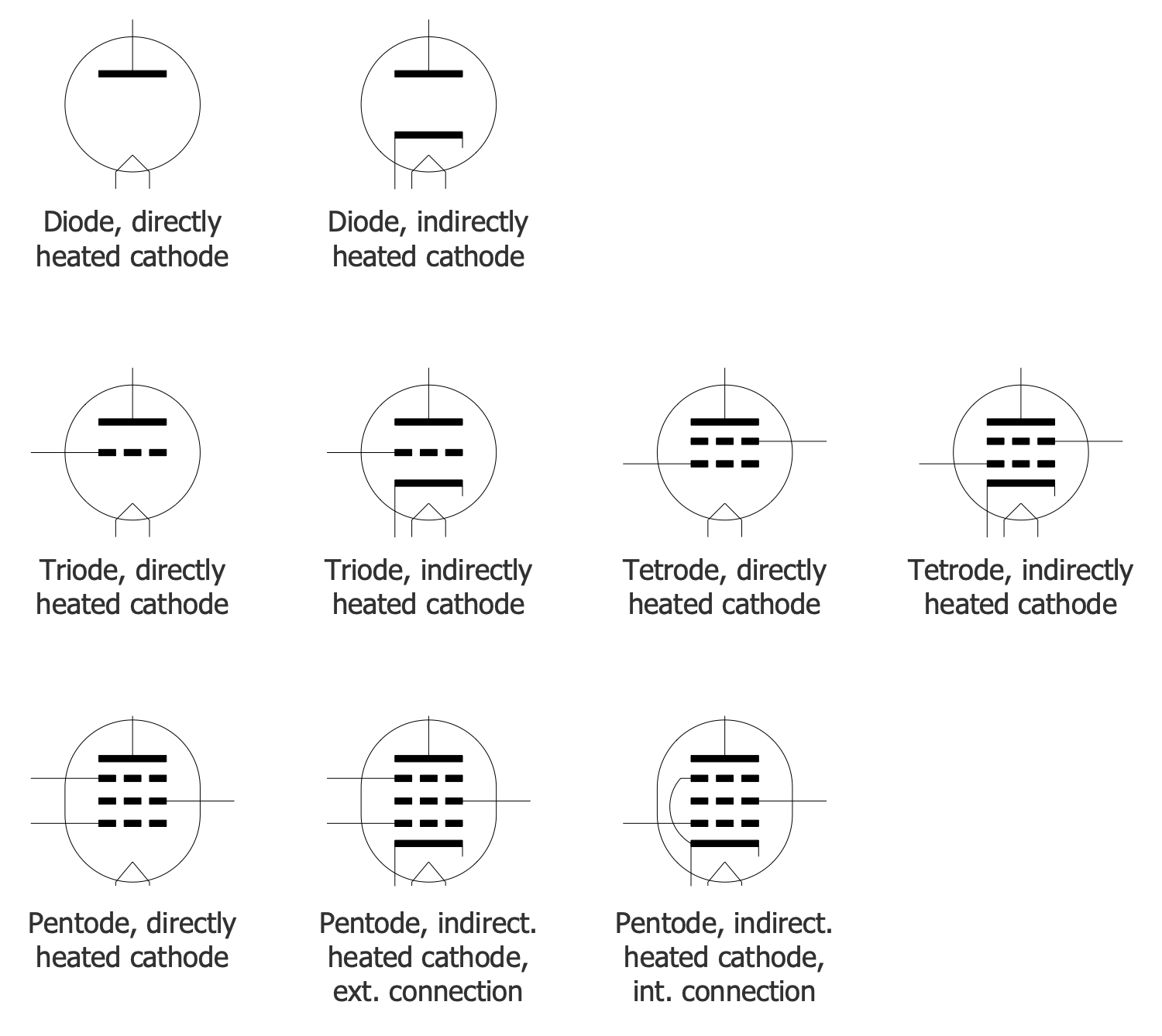
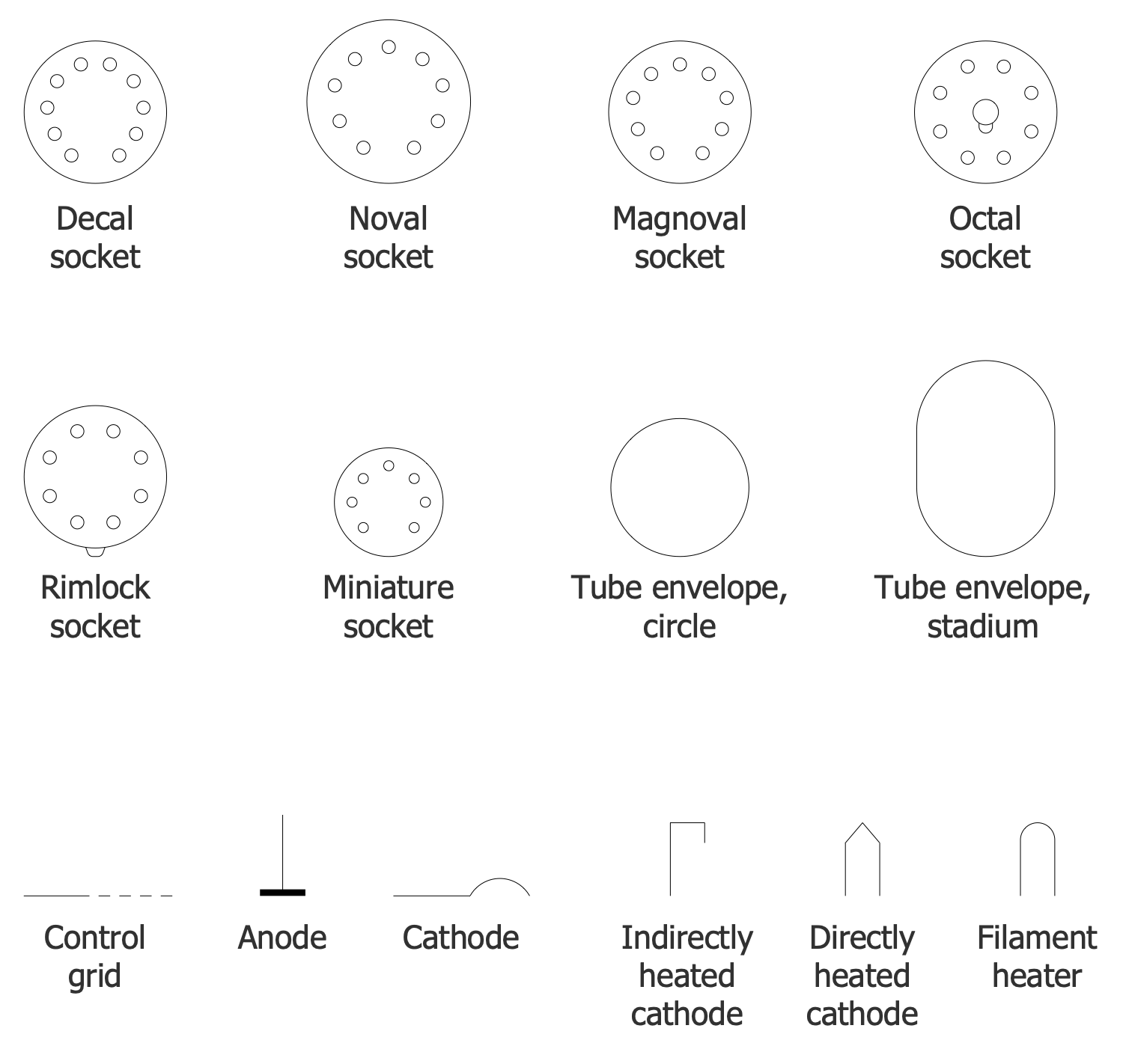
There are 4 stencil libraries containing 55 vector objects and 20 examples in the Electron Tube Circuits solution.
Design Elements — Gas Filled Tubes
Design Elements — Vacuum Tubes
Design Elements — Vacuum Tubes IEC
Design Elements — Vacuum Tube Sockets and Elements
Examples
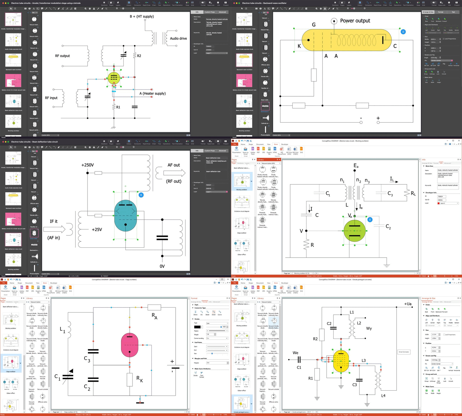
On this page you can see some samples created in the ConceptDraw DIAGRAM application using the Electron Tube Circuits solution. Some of the possibilities of the solution, as well as the professional results you can achieve, are shown here on this page.
All source documents are vector graphic documents that are always available for editing, viewing, and/or converting to various formats such as MS PowerPoint, PDF file, MS Visio, and many other graphics documents from ConceptDraw Solution Park or ConceptDraw STORE. The Electron Tube Circuits solution is available to all ConceptDraw DIAGRAM users to install and use while working in the ConceptDraw DIAGRAM drawing software.
Example 1: Anode Transformer Modulation Stage Using a Tetrode
This diagram was created in ConceptDraw DIAGRAM using a combination of libraries from the Electron Tube Circuits Solution. An experienced user spent 10 minutes creating this sample.
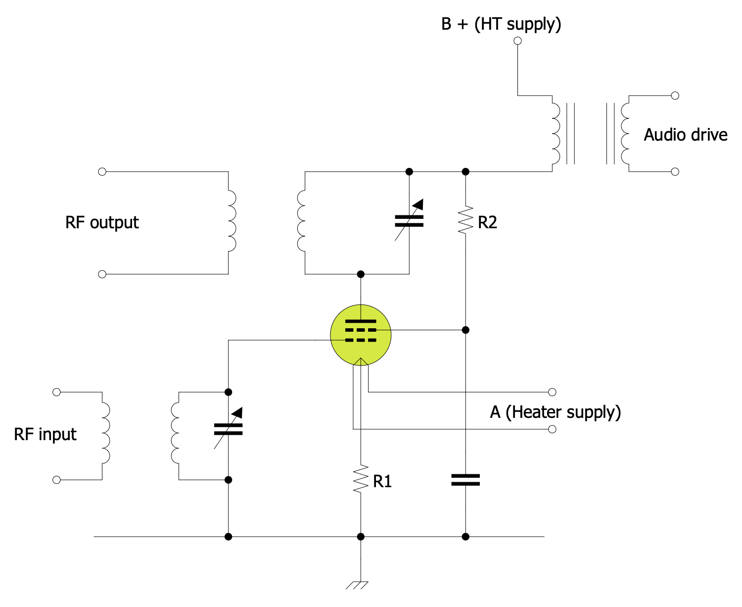
A wide range of different schemes was used for anode modulation (AM). This example demonstrates the AM plate modulators. In plate modulated systems, the voltage applied to the stage varies. Since the available output power depends on the supply voltage, it is modulated. transformer to change the anode voltage. can be applied for this purpose. The advantage of the transformer method is that the sound power can be fed into the RF stage and converted into RF power.
Example 2: Audion Circuit
This diagram was created in ConceptDraw DIAGRAM using a combination of libraries from the Electron Tube Circuits Solution. An experienced user spent 10 minutes creating this sample.
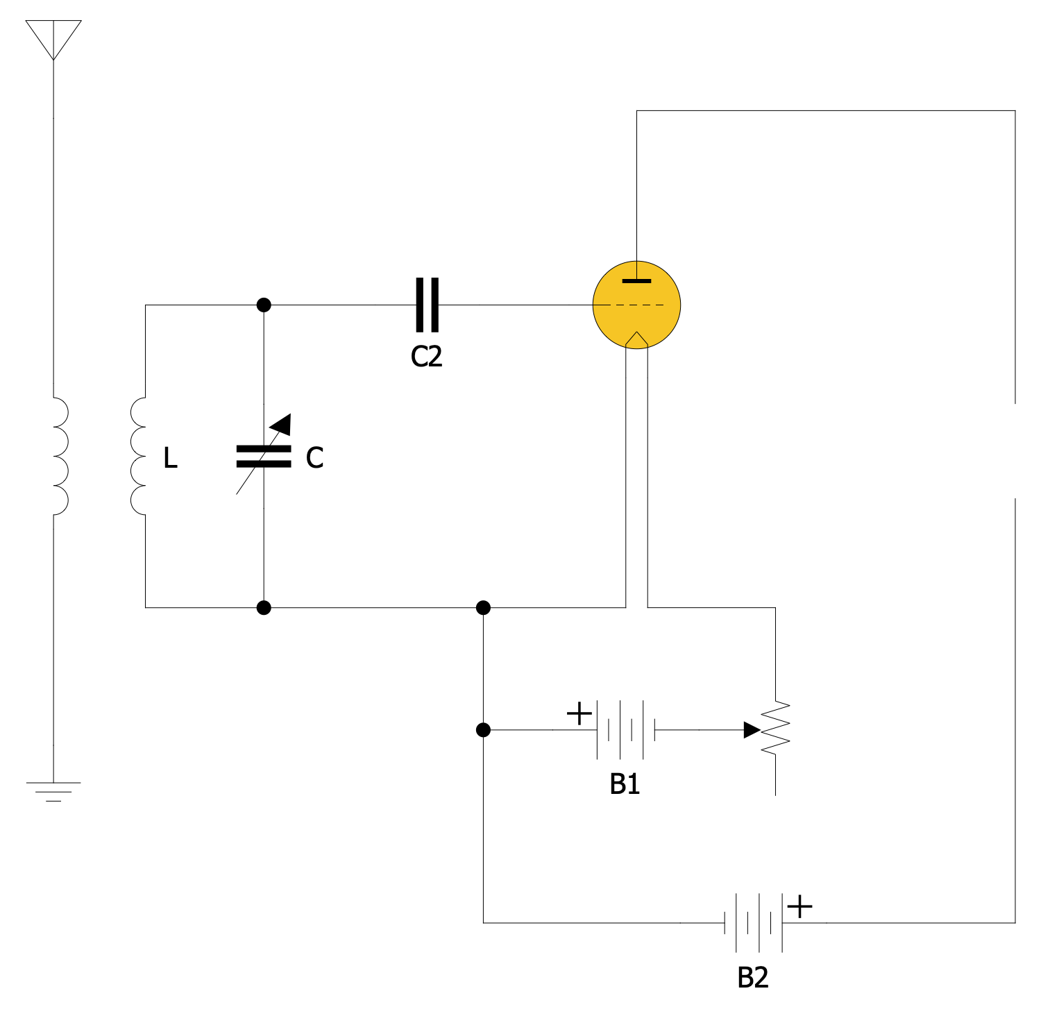
This example represents the Audion circuit. The Audion is an electronic detecting or amplifying vacuum tube invented by American electrical engineer Lee de Forest in 1906. The Audion tube allows the detection and amplification of weak radio signals. As the first triode vacuum tube, the Audion revolutionized radio broadcasting--and made it more practical. The Audion consists of an evacuated glass tube containing three electrodes: a heated filament, a grid, and a plate. It is important in the history of technology because it was the first widely used electronic device that could amplify. A low power signal at the grid could control much more power in the plate circuit.
Example 3: Audio Triode Cascode Circuit
This diagram was created in ConceptDraw DIAGRAM using a combination of libraries from the Electron Tube Circuits Solution. An experienced user spent 10 minutes creating this sample.
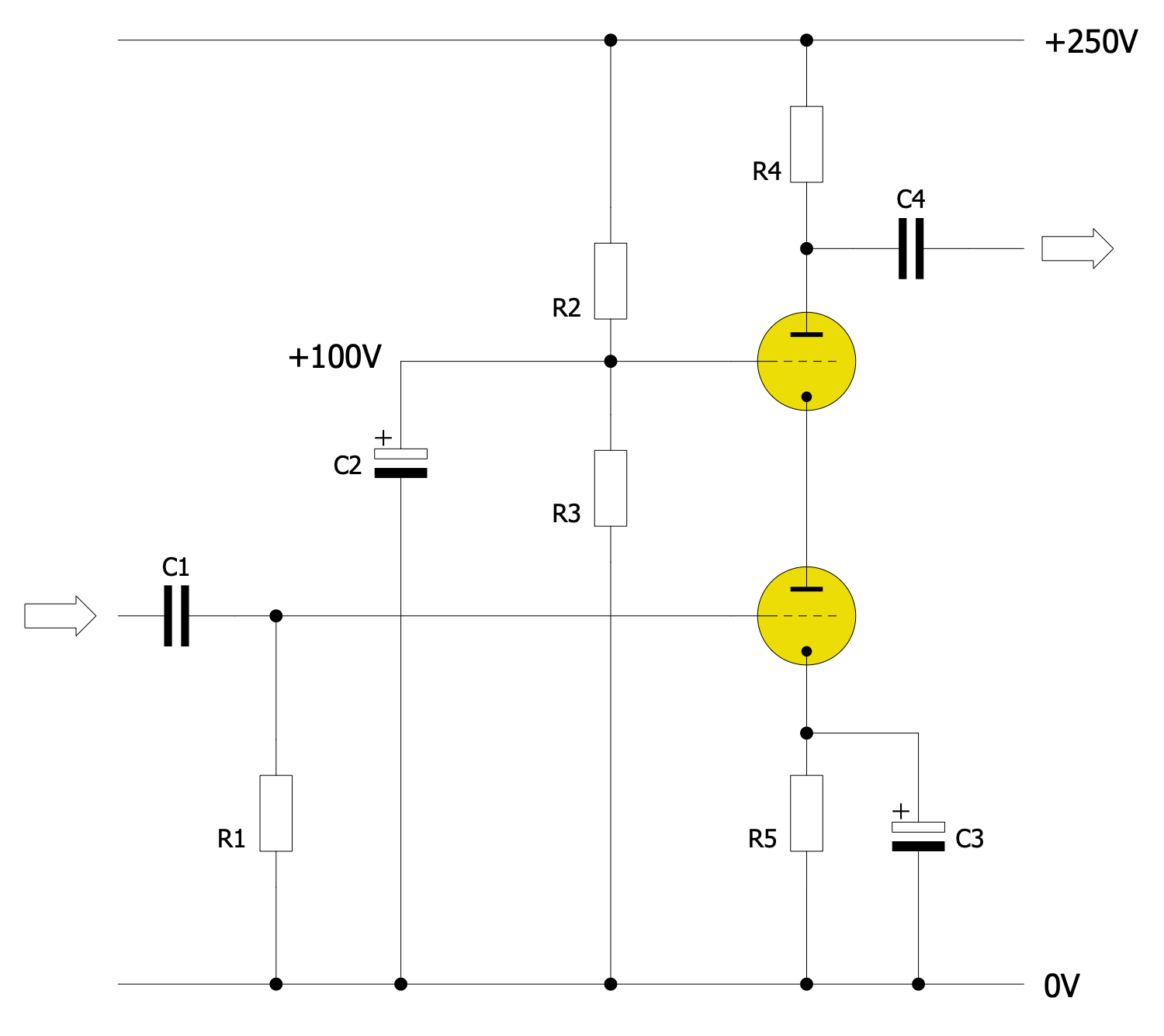
This circuit shows an example of a cascode amplifier with a common-source amplifier as the input stage. The cascode (a contraction of the phrase cascade to cathode) is a two-stage amplifier composed of a transconductance amplifier followed by a current buffer. In valve circuits, the cascode is often constructed from two triodes connected in series, with one operating as a common grid and thus acting as a voltage regulator, providing a nearly constant anode voltage to the other, which operates as a common cathode. This improves input-output isolation (or reverse transmission) by eliminating the Miller effect and thus contributes to much higher bandwidth, higher input impedance, high output impedance, and higher gain than a single-triode stage.
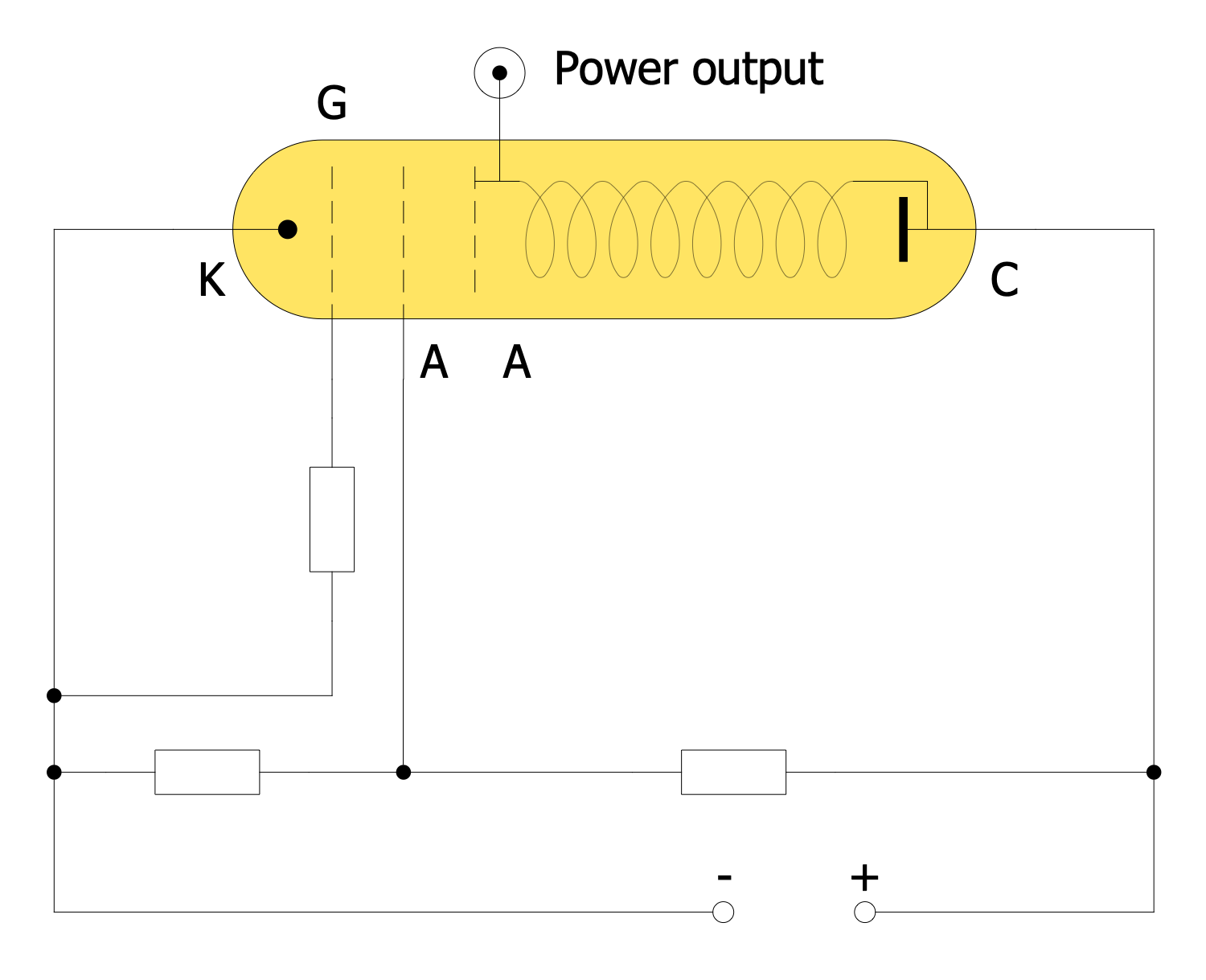
Example 4: Backward Wave Oscillator
This diagram was created in ConceptDraw DIAGRAM using a combination of libraries from the Electron Tube Circuits Solution. An experienced user spent 10 minutes creating this sample.
This example shows the Backward Wave Oscillator (BWO) circuit. BWO is used only for amplification and contains a helix as a delay line. A wave runs on this and interacts with an electron beam. However, the generated wave runs backward in BWOs on the helix, i.e opposite to the direction of the electron beam. The feedback of the oscillator is realized by the electron beam so that the speed changes induced in it at the exit become density changes due to the propagation time, which excite the end of the helix through their alternating electric field. The longitudinal magnetic field of a permanent magnet serves to focus or guide the electron beam.
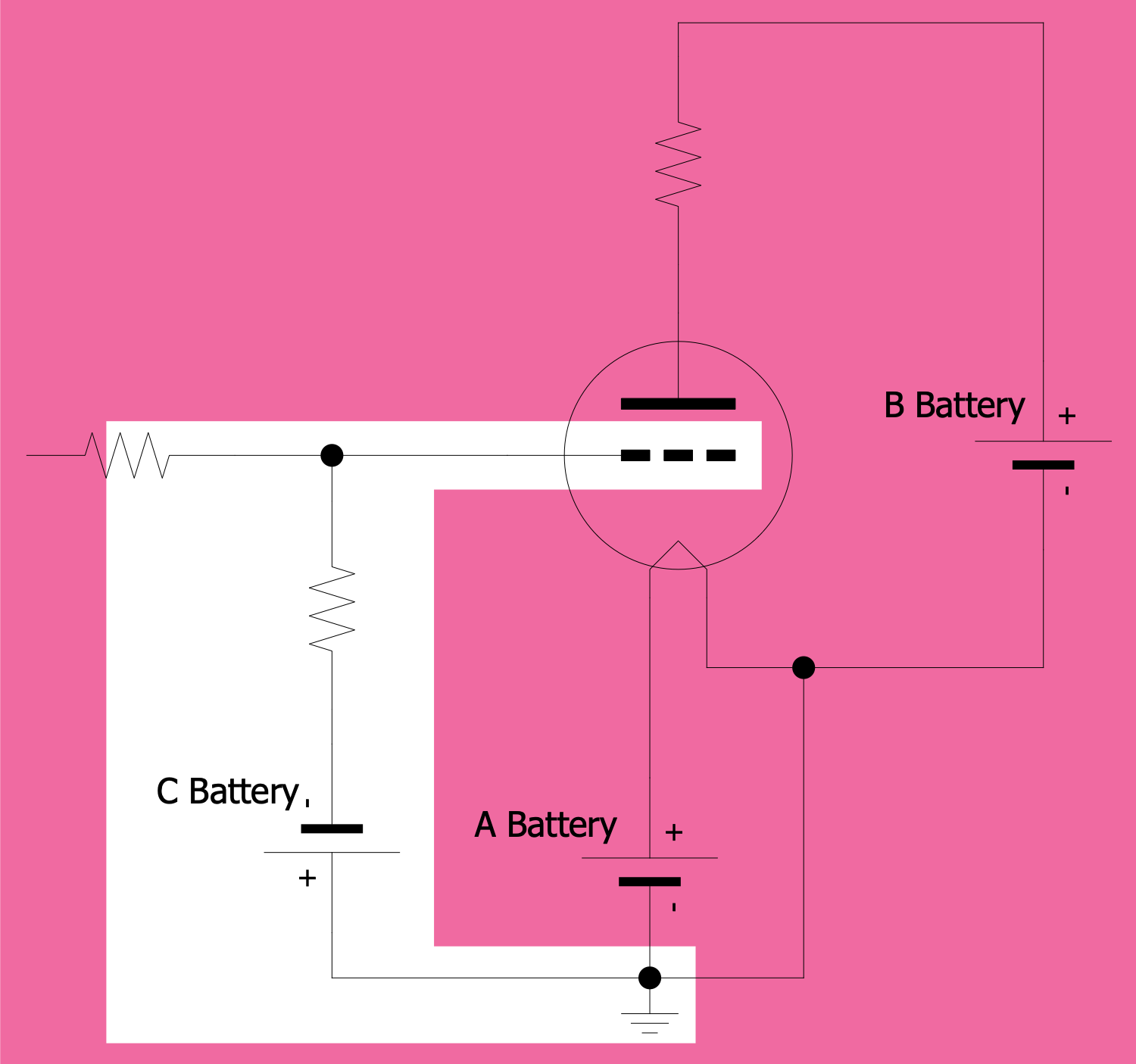
Example 5: Battery Circuit of a Triode Vacuum Tube
This diagram was created in ConceptDraw DIAGRAM using a combination of libraries from the Electron Tube Circuits Solution. An experienced user spent 10 minutes creating this sample.
This example shows the Battery Circuit of a Triode Vacuum Tube. Three different voltages are generally required, using three different batteries designated as the A, B, and C batteries. Each battery has a different designation depending on which tube element it was associated with.
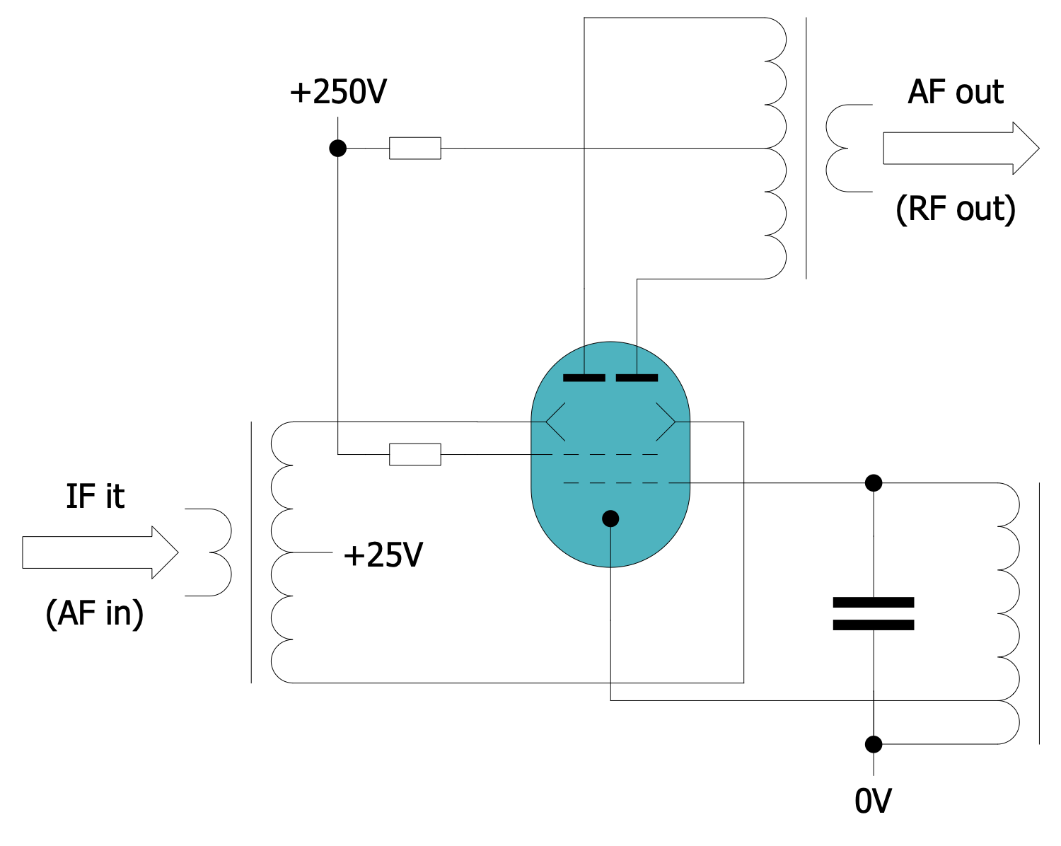
Example 6: Beam Deflection Tube Circuit
This diagram was created in ConceptDraw DIAGRAM using a combination of libraries from the Electron Tube Circuits Solution. An experienced user spent 10 minutes creating this sample.
This is an example of a beam deflection tube circuit. A beam deflection tube is a vacuum tube with an electron emitter, a beam intensity control grid, a screen grid, occasionally a suppressor grid, and two electrostatic deflection electrodes on opposite sides of the electron beam. It can be used as two-quadrant, single-balanced mixers or (de)modulators with linear qualities. The cathode and the first two grids can be made into an oscillator. Two beam deflection tubes can be combined into a double-balanced mixer. The beam deflection tube requires extensive shielding from external magnetic fields. Ballistic deflection transistors work on the same principle.
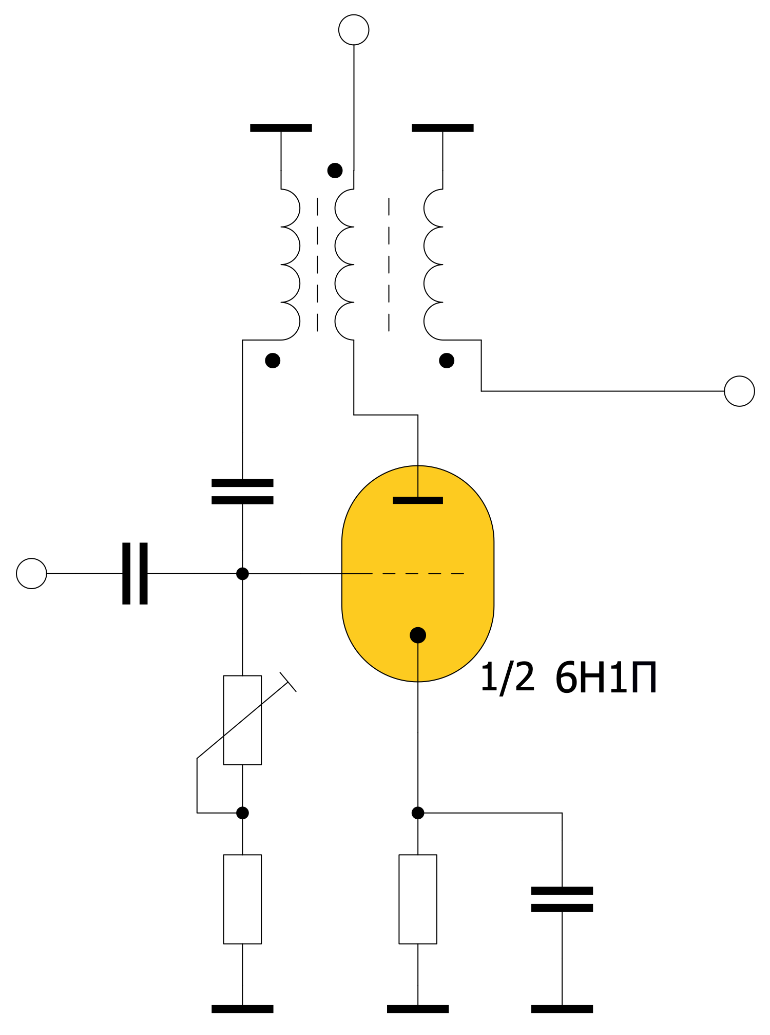
Example 7: Blocking Generator
This diagram was created in ConceptDraw DIAGRAM using a combination of libraries from the Electron Tube Circuits Solution. An experienced user spent 10 minutes creating this sample.
This diagram is an example of a blocking generator circuit. The blocking generator is a relaxation oscillator with deep transformer feedback. It outputs pulses of short duration with a long repetition period. It can operate in auto-generation and standby modes. The blocking generator circuit can be added to the generator circuit to improve stability. The blocking generator is characterized by a simple structure, easy timing, good stability, and the ability to obtain large pulse power with a relatively small average power.
Example 8: Blocking Oscillator
This diagram was created in ConceptDraw DIAGRAM using a combination of libraries from the Electron Tube Circuits Solution. An experienced user spent 10 minutes creating this sample.
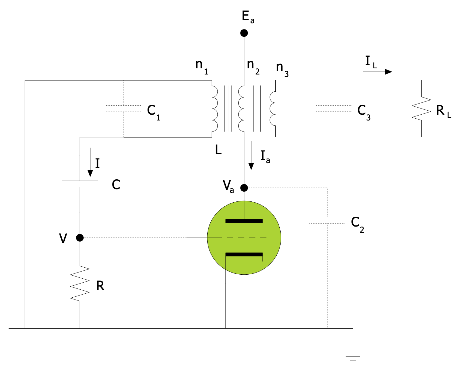
This diagram is an example of a blocking oscillator circuit. The blocking oscillator is a strong positive feedback transformer, a single tube (or single transistor) oscillator. It produces powerful, short (0.05-25 μs) and large amplitude (voltage over 100 seconds — several hundred currents) pulses. In this example of a simple blocking oscillator, the feedback circuit is a transformer, the pulse repetition period is determined by the resistance (R) by the capacitor discharge time (C). The power of the pulse front is highly dependent on the intermediate capacitance of the lamp (L). The generator block is a standard electronic lamp circuit (l). The output pulse of the blocking oscillator can be taken from a small resistor connected to the cathode (anode), or from the tertiary package of the transformer.
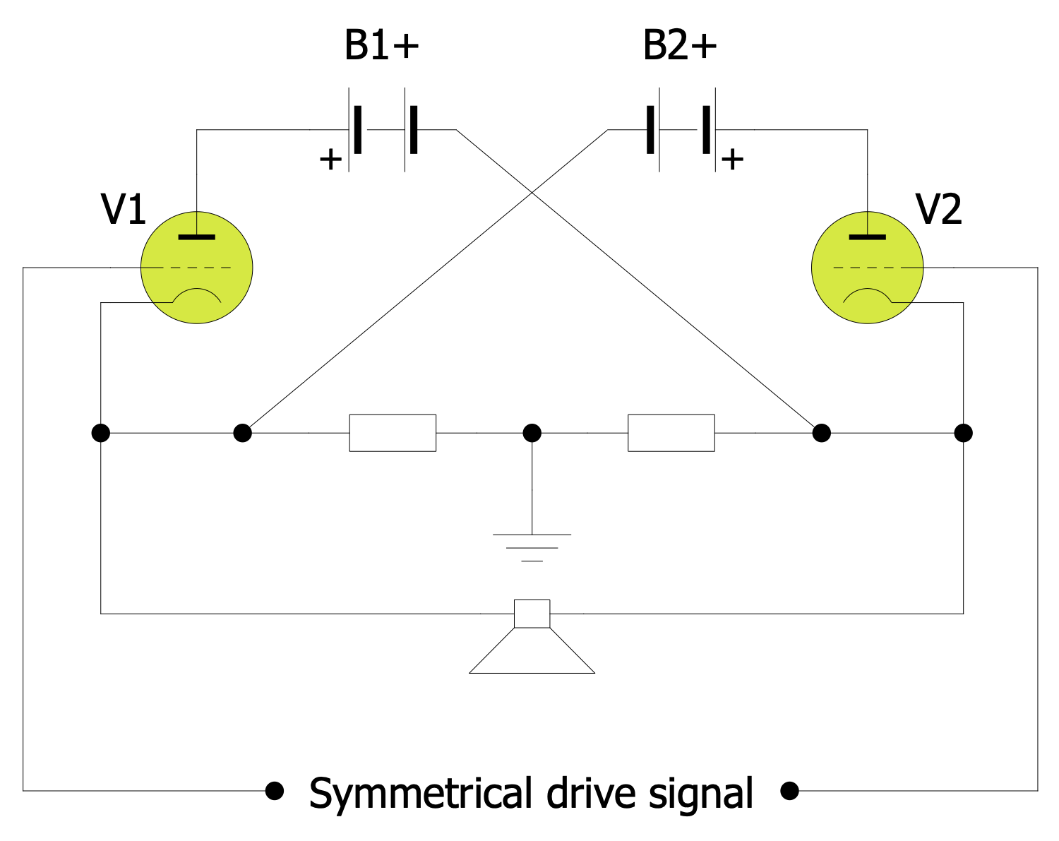
Example 9: Circlotron Circuit Diagram
This diagram was created in ConceptDraw DIAGRAM using a combination of libraries from the Electron Tube Circuits Solution. An experienced user spent 10 minutes creating this sample.
This diagram is an example of a circlotron valve amplifier circuit. Circlotron valve amplifier is a type of power amplifier utilizing a symmetrical cathode-coupled bridge circuit of the output stage. The electrical bridge of a circlotron is formed by a matched pair of triodes (V1, V2) and two floating power supplies ('B batteries'), B1+ and B2+. Grids of each triode are driven in opposite phases with a balanced, symmetrical input signal; differential current flows through the loudspeaker load and a simple, relatively high impedance, a resistor network that ties floating supplies to the ground. Tubes are usually fixed biased with an external negative power supply ('C battery'); each side normally has independent bias adjustment to compensate for minor tube mismatch.
Example 10: Clapp Oscillator
This diagram was created in ConceptDraw DIAGRAM using a combination of libraries from the Electron Tube Circuits Solution. An experienced user spent 10 minutes creating this sample.
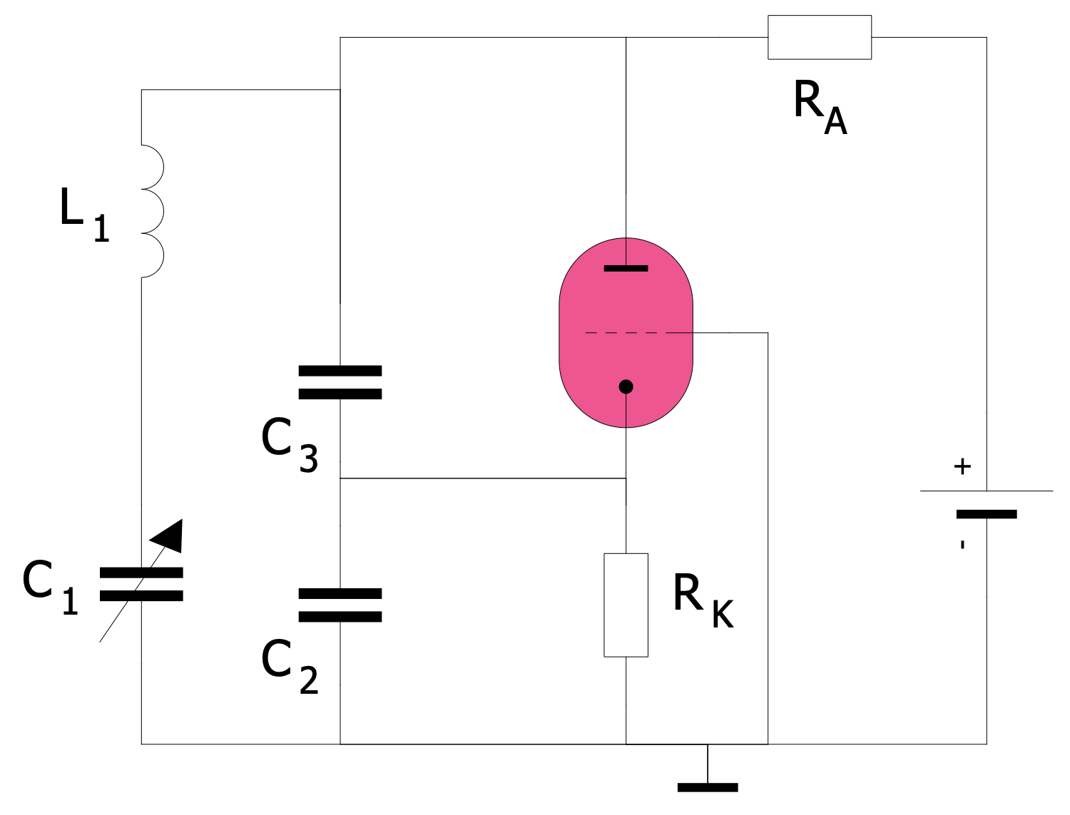
This diagram is an example of a Clapp oscillator circuit. The Clapp oscillator was developed by James K. Clapp in 1948. Its peculiarity is that it uses an electron tube as an amplifier. The frequency-determining oscillating circuit consists of the coil and three series-connected capacitors. In this case, the frequency-determining capacitor C1 is not included in the positive feedback. The other two capacitors C2 and C3 form a voltage divider, on which part of the oscillating circuit voltage is fed back to the cathode and thus amplified. The circuit is suitable for high frequencies where high-frequency stability is required and the coil-tapping oscillator is not practical.
Example 11: Dual Control Grid Tetrode Frequency Changer
This diagram was created in ConceptDraw DIAGRAM using a combination of libraries from the Electron Tube Circuits Solution. An experienced user spent 10 minutes creating this sample.
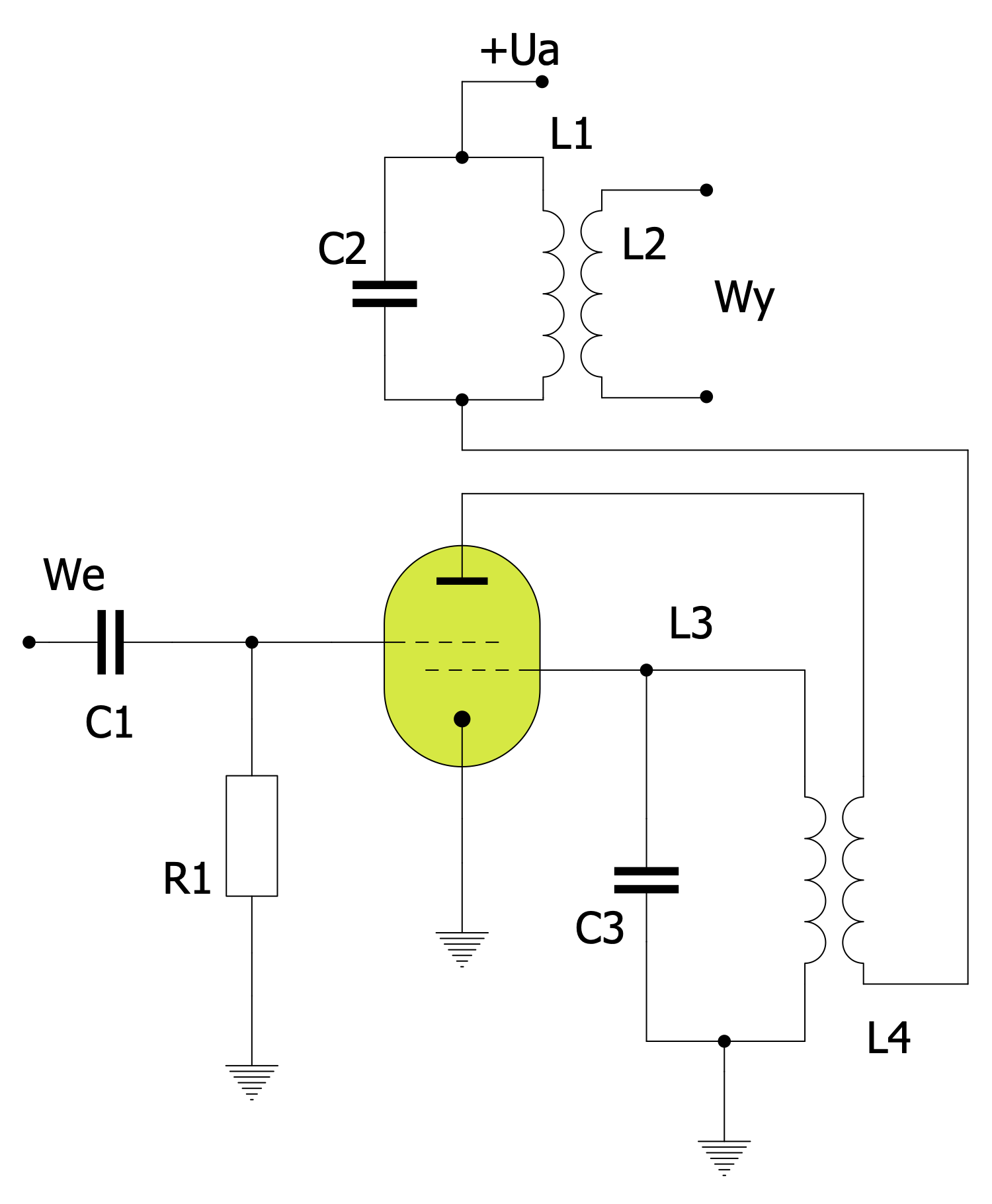
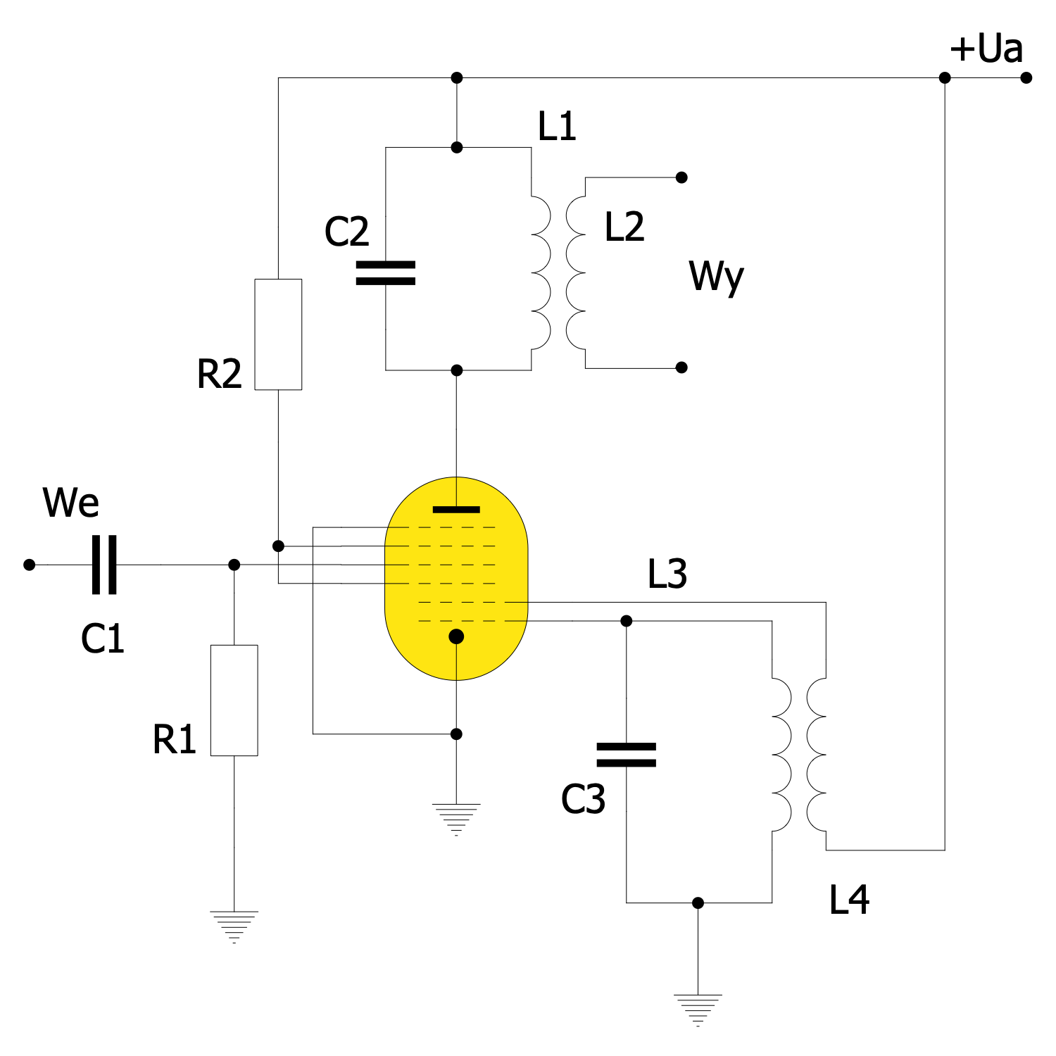
A tetrode is a type of electronic tube with four electrodes: an anode, a cathode, and two grids located between the anode and cathode. This diagram represents a dual control grid tetrode frequency changer. The frequency conversion circuit is implemented on a tetrode. The received signal is applied to the input We, and a heterodyne system is built into the first grid circuit with a frequency determined by the resonant circuit L3C3. The output signal is emitted by the resonant circuit L1C2.
Example 12: Edison Effect
This diagram was created in ConceptDraw DIAGRAM using a combination of libraries from the Electron Tube Circuits Solution. An experienced user spent 10 minutes creating this sample.
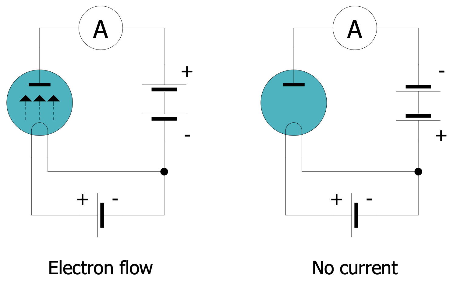
The thermionic effect consists of the thermally induced emission of charged particles (electrons or ions), by a material, sometimes a metal heated to high temperature. A classic example of thermionic emission is that which occurs in electron tubes, where electrons are emitted from a high-temperature metal cathode in a tube in which the vacuum has been created (known as the Effect Edison). This diagram depicts the Edison effect in a diode. The diode is presented in two configurations, the first pass current, and the second does not. Note that the arrows indicate the direction of the electron flow, not the conventional direction of the electric current, which is opposite to it.
Example 13: Heptode Pentagrid Converter Circuits
This diagram was created in ConceptDraw DIAGRAM using a combination of libraries from the Electron Tube Circuits Solution. An experienced user spent 10 minutes creating this sample.
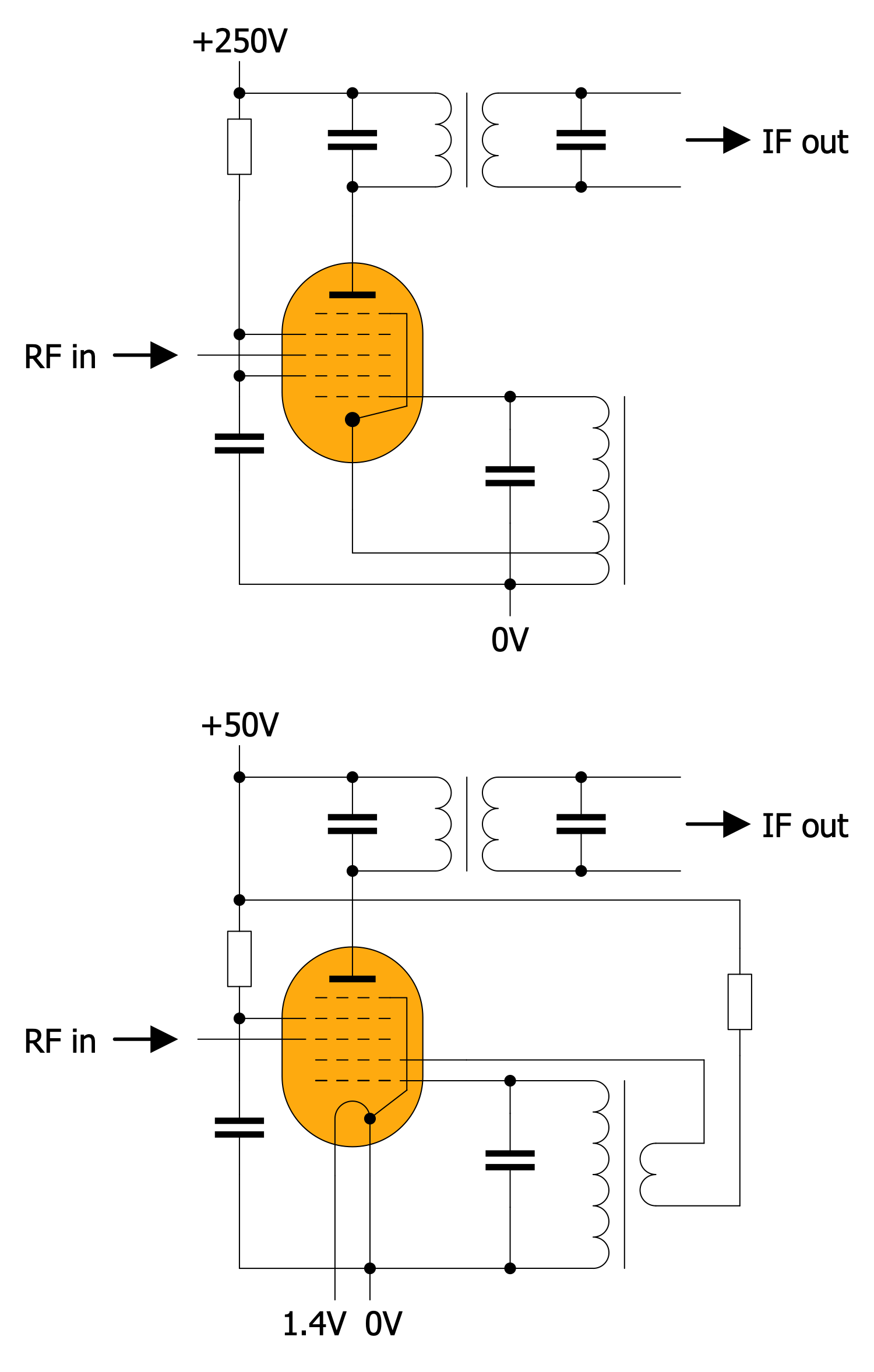
The pentagrid converter is a type of radio receiving valve (vacuum tube) with five grids used as the frequency mixer stage of a superheterodyne radio receiver. Typical pentagrid connection as mixer/oscillator. Top connection to Hartley generator for indirectly heated lamps (6H31), bottom connection to Miller generator for directly heated lamps (batteries) (1H33). An anode voltage of 45V is quite enough here.
Example 14: Octode Pentagrid Converter
This diagram was created in ConceptDraw DIAGRAM using a combination of libraries from the Electron Tube Circuits Solution. An experienced user spent 10 minutes creating this sample.
This diagram represents the octode-based pentagrid-converter circuit. The pentagrid converter is a type of radio receiving valve (vacuum tube) with five grids used as the frequency mixer stage of a superheterodyne radio receiver. The octode is a tube with eight electrodes — cathode, anode, and 6 grids. It was used (similarly to the heptode) mainly in superheterodyne, where it provides mixing and was also the source of one of the frequencies.
Example 15: Photomultiplier Voltage Divider Circuit
This diagram was created in ConceptDraw DIAGRAM using a combination of libraries from the Electron Tube Circuits Solution. An experienced user spent 10 minutes creating this sample.
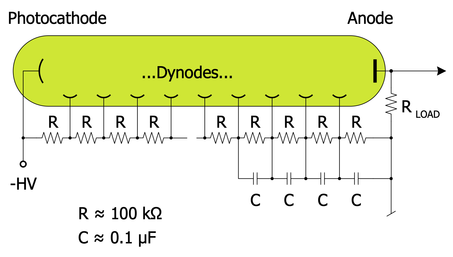
Photomultipliers are a type of vacuum tubes, more specifically vacuum phototubes, which are extremely sensitive light detectors in the ultraviolet, visible, and near-infrared ranges of the electromagnetic spectrum. This diagram illustrates the required voltage distribution across multiple dynodes provided by a string of voltage dividers. In this example, the photocathode is held at a negative high voltage on the order of 1000V and the anode potential is very close to ground potential. The capacitors on the last few dynodes act as local charge reservoirs, helping to maintain the voltage across the dynodes while the electron avalanches propagate through the tube.
Example 16: Single Ended Triode Power Stage
This diagram was created in ConceptDraw DIAGRAM using a combination of libraries from the Electron Tube Circuits Solution. An experienced user spent 10 minutes creating this sample.
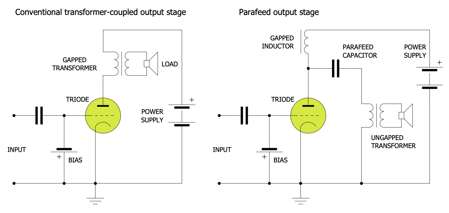
A single-ended triode (SET) is a vacuum tube electronic amplifier that uses a single triode to produce an output. This diagram represents a typical triode audio power amplifier circuit. Single-ended amplifiers normally operate in Class A. The triode is biased to Class A operation by applying a suitable negative bias voltage to its input control grid (see diagram), or by raising the cathode potential with biasing components. An example of such a device is the Antique Sound Lab MG-SI15DT — the stereo class A single-ended design with KT88 kinkless tetrodes which produces 15W of output power per channel, and 5W when triode-connected.
Example 17: Tetrode Mixer
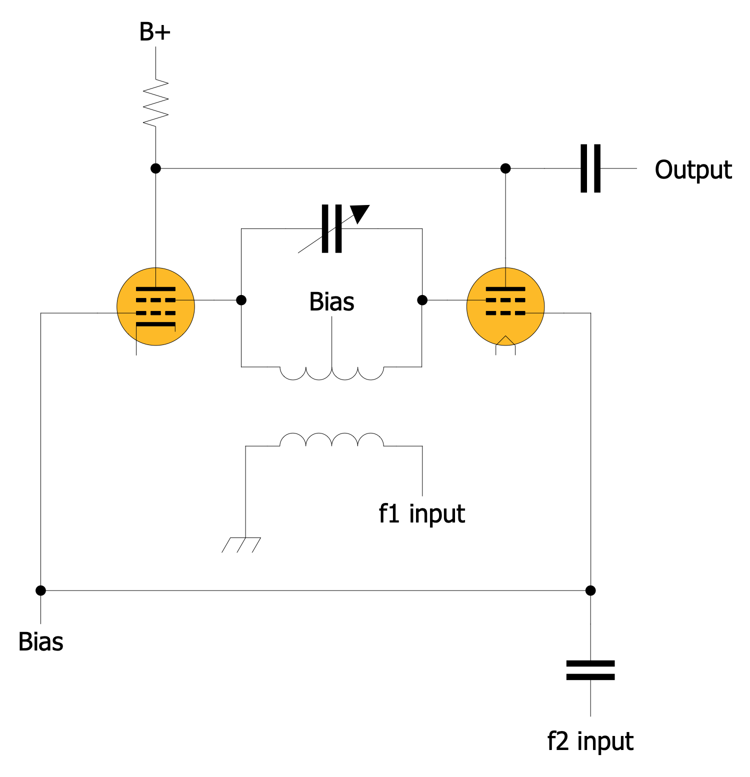
This diagram was created in ConceptDraw DIAGRAM using a combination of libraries from the Electron Tube Circuits Solution. An experienced user spent 10 minutes creating this sample.
Using a balanced mixer a double sideband signal is generated. This is an example of replacing a simple mixer with a balanced mixer. The point is mixers having the equation {I = E1. E2} are connected so that the current outputs are connected to the two ends of the coil, then the total current flowing through the coil is the difference between the outputs of the two mixer stages. If the f1 drive for one of the mixers is phase-shifted by 180o then the overall system will be a balanced mixer.
Example 18: Triode Common Cathode Gain Stage
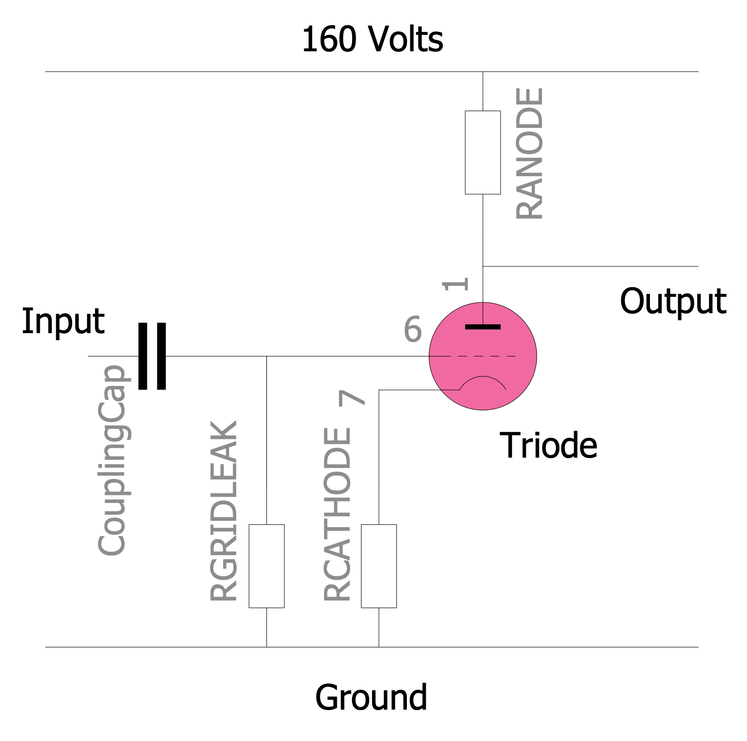
This diagram was created in ConceptDraw DIAGRAM using a combination of libraries from the Electron Tube Circuits Solution. An experienced user spent 10 minutes creating this sample.
The main gain stage for a valve amplifier is the auto-biased common cathode stage, in which the anode resistor, tube, and cathode resistor form a voltage divider on the power rails. Almost all audio preamplifier circuits are built using common cathode stages. The signal is passed from stage to stage via a coupling capacitor or transformer, although in rare cases a direct connection is used.
Example 19: Tube Push Pull Power Amplifier for Audio
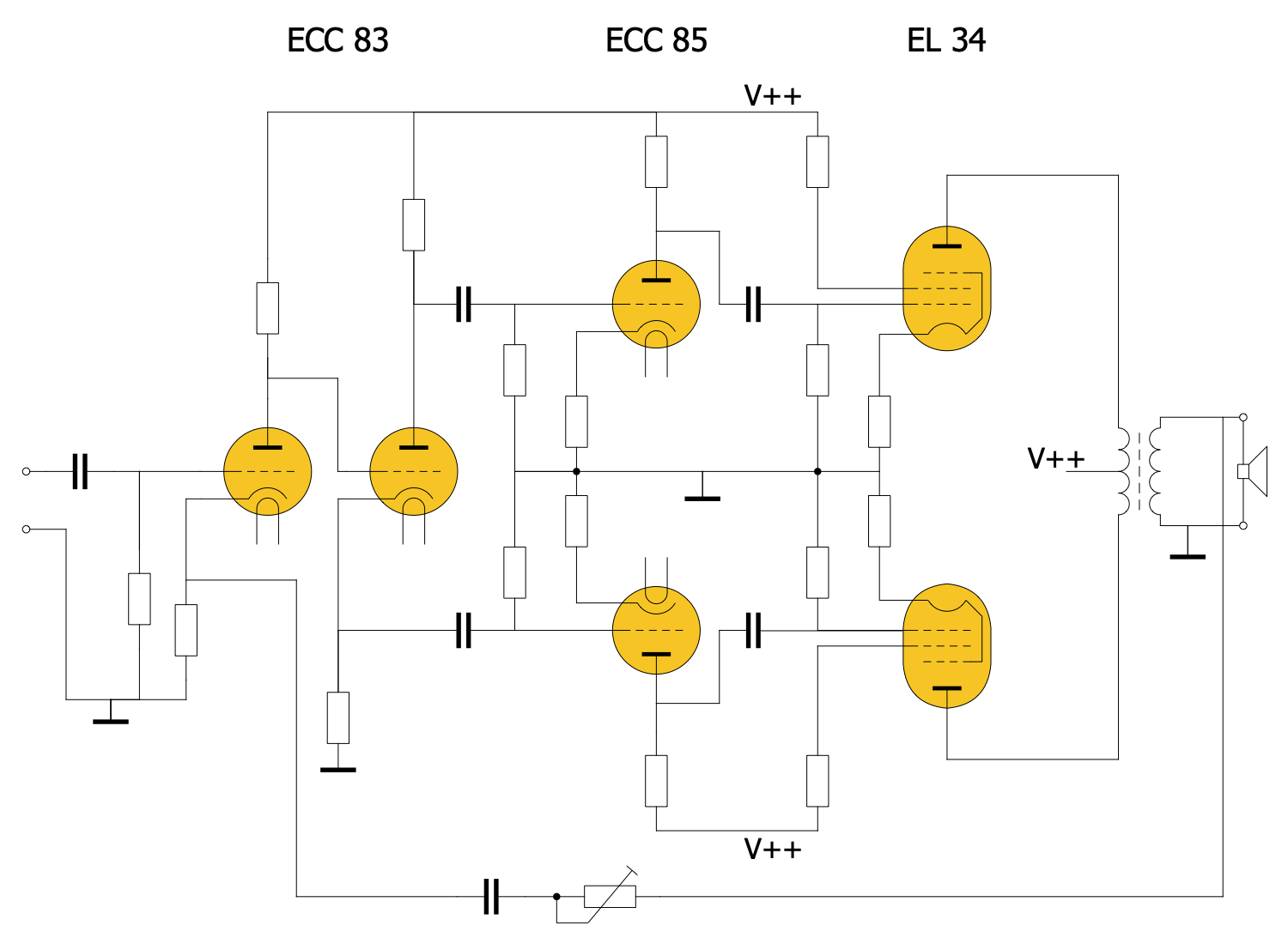
This diagram was created in ConceptDraw DIAGRAM using a combination of libraries from the Electron Tube Circuits Solution. An experienced user spent 10 minutes creating this sample.
A push-pull amplifier is a type of electronic circuit that uses a pair of active devices that alternately supply current to, or absorb current from, a connected load. This is an example of a conceptual circuit of a power amplifier with a split-load phase inverter and push-pull EL34 pentodes endstage. A vacuum tube amplifier uses a center-tapped output transformer to combine the outputs of tubes connected in push-pull mode.
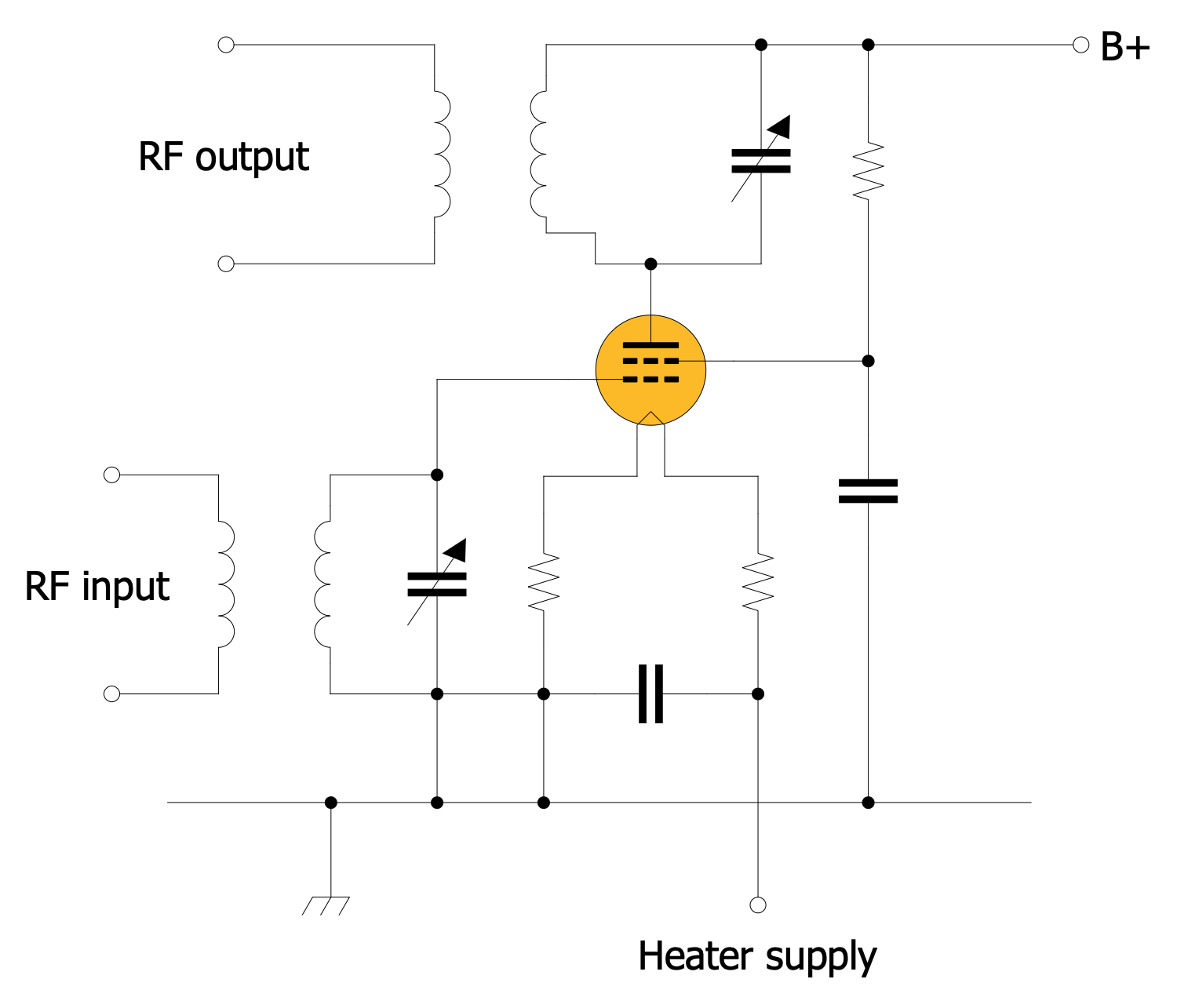
Example 20: Tuned Grid RF Tetrode Amplifier
This diagram was created in ConceptDraw DIAGRAM using a combination of libraries from the Electron Tube Circuits Solution. An experienced user spent 10 minutes creating this sample.
This is an example of a tuned grid RF tetrode amplifier. The tetrode has a screen grid that sits between the anode and the first grid. The screen grid serves to increase the stage gain while also providing shielding which increases the stability of the circuit by reducing the effective capacitance between the first grid and the anode. The valve anode is connected to the LC circuit to tune the plate circuit into resonance. The antenna can be powered via an optional inductive connection.
Inside
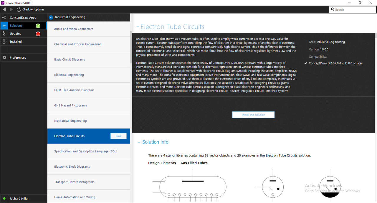
What I Need to Get Started
Both ConceptDraw DIAGRAM diagramming and drawing software and the Electron Tube Circuits solution can help creating the illustrations the technical documentation of an engineering projects you need. The Electron Tube Circuits solution can be found in the Industrial Engineering area of ConceptDraw STORE application that can be downloaded from this site. Make sure that both ConceptDraw DIAGRAM and ConceptDraw STORE applications are installed on your computer before you get started.
How to install
After ConceptDraw STORE and ConceptDraw DIAGRAM are downloaded and installed, you can install the Electron Tube Circuits solution from the ConceptDraw STORE.
Start Using
To make sure that you are doing it all right, use the pre-designed symbols from the stencil libraries from the solution to make your drawings look smart and professional. Also, the pre-made examples from this solution can be used as drafts so your own drawings can be based on them. Using the samples, you can always change their structures, colors and data.
