- Electric and Telecom Plans Free
- Fire and Emergency Plans Free
- Floor Plans Free
- Plant Layout Plans Free
- School and Training Plans Free
- Seating Plans Free
- Security and Access Plans Free
- Site Plans Free
- Sport Field Plans Free
- Business Process Diagrams Free
- Business Process Mapping Free
- Classic Business Process Modeling Free
- Cross-Functional Flowcharts Free
- Event-driven Process Chain Diagrams Free
- IDEF Business Process Diagrams Free
- Logistics Flow Charts Free
- Workflow Diagrams Free
- ConceptDraw Dashboard for Facebook Free
- Mind Map Exchange Free
- MindTweet Free
- Note Exchange Free
- Project Exchange Free
- Social Media Response Free
- Active Directory Diagrams Free
- AWS Architecture Diagrams Free
- Azure Architecture Free
- Cisco Network Diagrams Free
- Cisco Networking Free
- Cloud Computing Diagrams Free
- Computer Network Diagrams Free
- Google Cloud Platform Free
- Interactive Voice Response Diagrams Free
- Network Layout Floor Plans Free
- Network Security Diagrams Free
- Rack Diagrams Free
- Telecommunication Network Diagrams Free
- Vehicular Networking Free
- Wireless Networks Free
- Comparison Dashboard Free
- Composition Dashboard Free
- Correlation Dashboard Free
- Frequency Distribution Dashboard Free
- Meter Dashboard Free
- Spatial Dashboard Free
- Status Dashboard Free
- Time Series Dashboard Free
- Basic Circle-Spoke Diagrams Free
- Basic Circular Arrows Diagrams Free
- Basic Venn Diagrams Free
- Block Diagrams Free
- Concept Maps Free
- Family Tree Free
- Flowcharts Free
- Basic Area Charts Free
- Basic Bar Graphs Free
- Basic Divided Bar Diagrams Free
- Basic Histograms Free
- Basic Line Graphs Free
- Basic Picture Graphs Free
- Basic Pie Charts Free
- Basic Scatter Diagrams Free
- Aerospace and Transport Free
- Artwork Free
- Audio, Video, Media Free
- Business and Finance Free
- Computers and Communications Free
- Holiday Free
- Manufacturing and Maintenance Free
- Nature Free
- People Free
- Presentation Clipart Free
- Safety and Security Free
- Analog Electronics Free
- Audio and Video Connectors Free
- Basic Circuit Diagrams Free
- Chemical and Process Engineering Free
- Digital Electronics Free
- Electrical Engineering Free
- Electron Tube Circuits Free
- Electronic Block Diagrams Free
- Fault Tree Analysis Diagrams Free
- GHS Hazard Pictograms Free
- Home Automation and Wiring Free
- Mechanical Engineering Free
- One-line Diagrams Free
- Power Сircuits Free
- Specification and Description Language (SDL) Free
- Telecom and AV Circuits Free
- Transport Hazard Pictograms Free
- Data-driven Infographics Free
- Pictorial Infographics Free
- Spatial Infographics Free
- Typography Infographics Free
- Calendars Free
- Decision Making Free
- Enterprise Architecture Diagrams Free
- Fishbone Diagrams Free
- Organizational Charts Free
- Plan-Do-Check-Act (PDCA) Free
- Seven Management and Planning Tools Free
- SWOT and TOWS Matrix Diagrams Free
- Timeline Diagrams Free
- Australia Map Free
- Continent Maps Free
- Directional Maps Free
- Germany Map Free
- Metro Map Free
- UK Map Free
- USA Maps Free
- Customer Journey Mapping Free
- Marketing Diagrams Free
- Matrices Free
- Pyramid Diagrams Free
- Sales Dashboard Free
- Sales Flowcharts Free
- Target and Circular Diagrams Free
- Cash Flow Reports Free
- Current Activities Reports Free
- Custom Excel Report Free
- Knowledge Reports Free
- MINDMAP Reports Free
- Overview Reports Free
- PM Agile Free
- PM Dashboards Free
- PM Docs Free
- PM Easy Free
- PM Meetings Free
- PM Planning Free
- PM Presentations Free
- PM Response Free
- Resource Usage Reports Free
- Visual Reports Free
- House of Quality Free
- Quality Mind Map Free
- Total Quality Management TQM Diagrams Free
- Value Stream Mapping Free
- Astronomy Free
- Biology Free
- Chemistry Free
- Language Learning Free
- Mathematics Free
- Physics Free
- Piano Sheet Music Free
- Android User Interface Free
- Class Hierarchy Tree Free
- Data Flow Diagrams (DFD) Free
- DOM Tree Free
- Entity-Relationship Diagram (ERD) Free
- EXPRESS-G data Modeling Diagram Free
- IDEF0 Diagrams Free
- iPhone User Interface Free
- Jackson Structured Programming (JSP) Diagrams Free
- macOS User Interface Free
- Object-Role Modeling (ORM) Diagrams Free
- Rapid UML Free
- SYSML Free
- Website Wireframe Free
- Windows 10 User Interface Free
Green Energy
Green energy is an energy coming from renewable natural resources like sunlight, wind, water, tides, rain, geothermal heat, and more. Green energy has great advantages and is an excellent alternative to non-renewable energy. It is an inexhaustible energy source, sustainable and self-sufficient. Green energy sources are usually replenished naturally and help to reduce energy consumption costs. Moreover, green energy sources sometimes are a single available way to take energy for remote and rural areas.
As the use of traditional energy resources like coal, oil and natural gas expands the impact of humans on the environment and the problem of pollution increases. The negative consequences are obvious and the importance of transitioning to renewable sources increases day by day and becomes clear to consumers. Green energy is clean and environmentally friendly. It doesn't pollute, doesn't harm the environment, and doesn't cause greenhouse gases or carbon emissions. This helps fight global warming and slows down climate change.
Green energy is able to replace fossil fuels in all major areas of use including electricity, vehicles, water heating, etc. Continuous research and developments are undertaken in the energy field and a lot of modern perspective technologies are invented. Advances in technology ensure that the cost of various clean energy equipment like wind turbines, solar panels, etc., is constantly decreasing. There are many types of green energy generated by large variety of sources. It comprises power produced by solar, wind, geothermal, hydroelectric, wave, tidal, and alternative fuel sources, including hydrogen fuel, biomass, biogas, biohydrogen, and biofuel. The use of a specific type of green energy depends on the region and environment it is used. Solar power, wind power, hydropower, geothermal energy, biogas, and biomass are the most common types of green energy.
Solar energy is a common form of renewable energy. It is a clean source of energy coming directly from the sun. Solar energy is collected, predominantly by solar panels. They convert it into usable electricity. Solar panels are filled by photovoltaic cells creating an electrical current at the light hit on them through the photoelectric effect. The current is then passed through the inverter and converted into ready-to-use alternating current. Thermal technology is an additional method of generating solar thermal energy commonly used to heat fluids.
Hydropower is produced using the flow of water in rivers, streams, dams, tides in the oceans, rainfall, evaporation, etc. The special installations are placed underwater, capture the energy contained within flowing water and convert it into electricity. The highest amount of energy is achieved by forcing water to flow through a narrow path. For this purpose, reservoirs and dams are built. The water streams from the dam through the intake with incredible speed, spins a turbine activating a generator to produce electricity. Due to its efficiency, hydroelectricity is one of the most popular today and over 70% of renewable energy production is hydropower.
Wind power uses the energy of the air stream to propel turbine generators to generate electricity. The energy generators are mostly placed in high wind velocity locations and in high altitudes. The stronger winds produce more energy and the high-altitude locations provide the best conditions for the strongest winds. Wind power generation equipment is easier to construct than hydropower one and this kind of energy is more cost-efficient than solar.
Geothermal energy is generated by the natural heat of the Earth. An enormous amount of thermal energy has been accumulated under the earth's crust since the formation of the planet and as a result of the radioactive decay of minerals. Geothermal energy production is the only green energy that does not depend on atmospheric conditions and is not intermittent. Biogas uses waste products to produce energy and is a byproduct of their decomposition. Among the used organic matter are food, agricultural waste, household waste, agro-industrial waste, sewage, manure, etc. Being stored in containers without oxygen these materials cause the fermentation and release of gases like methane, carbon dioxide, and more. Methane is used to produce electricity and fuel. The rest waste is used as fertilizers on farms.
Biomass energy is a conversion of manufacturing by-products, organic plants, or specifically produced materials like, for example, corn ethanol into electricity as a result of their burning. It is based on the use of sun energy stored in plants and animals, mostly in the form of sugar or cellulose. The by-products include wood chips and fragments, sawdust, combustible agricultural waste, animal manure, leftover sugar, and more. The heat energy from their burning is turned into electricity. And due to the energy from the sun stored at them, these materials cause far fewer greenhouse gas emissions than petroleum-based fuel sources.
Green Energy solution extends the ConceptDraw DIAGRAM functionality with a large collection of vector design icons, pictograms, and clipart useful to design green energy infographics and illustrations of any kind. Create overview infographics about solar power, wind power, hydropower, tidal power and other renewable and cleaner energy sources. Compare visually different types of energy or data over several years in one chart. Develop detailed infographics about power generation mechanisms, how do solar panels work, wind and tidal turbines, and more specialized power generation equipment.
-
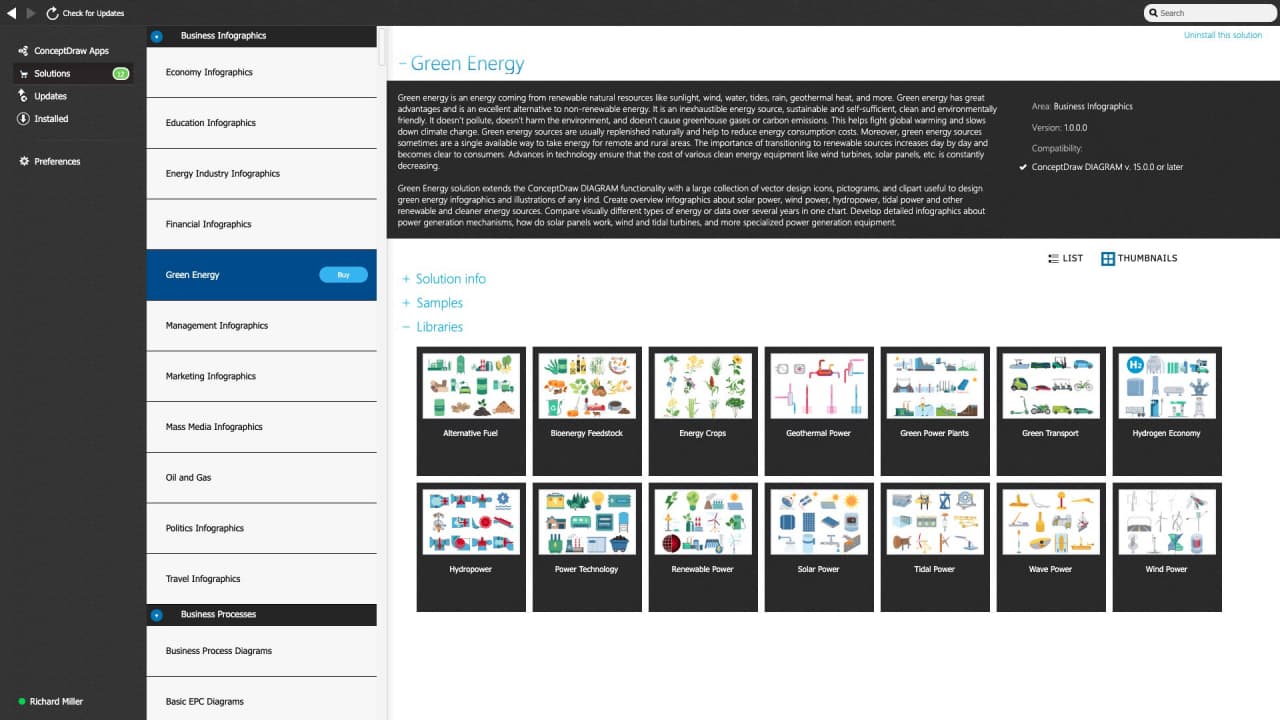
Buy this solution $25 -
Solution Requirements - This solution requires the following products to be installed:
-
Support for this Solution -
Helpdesk
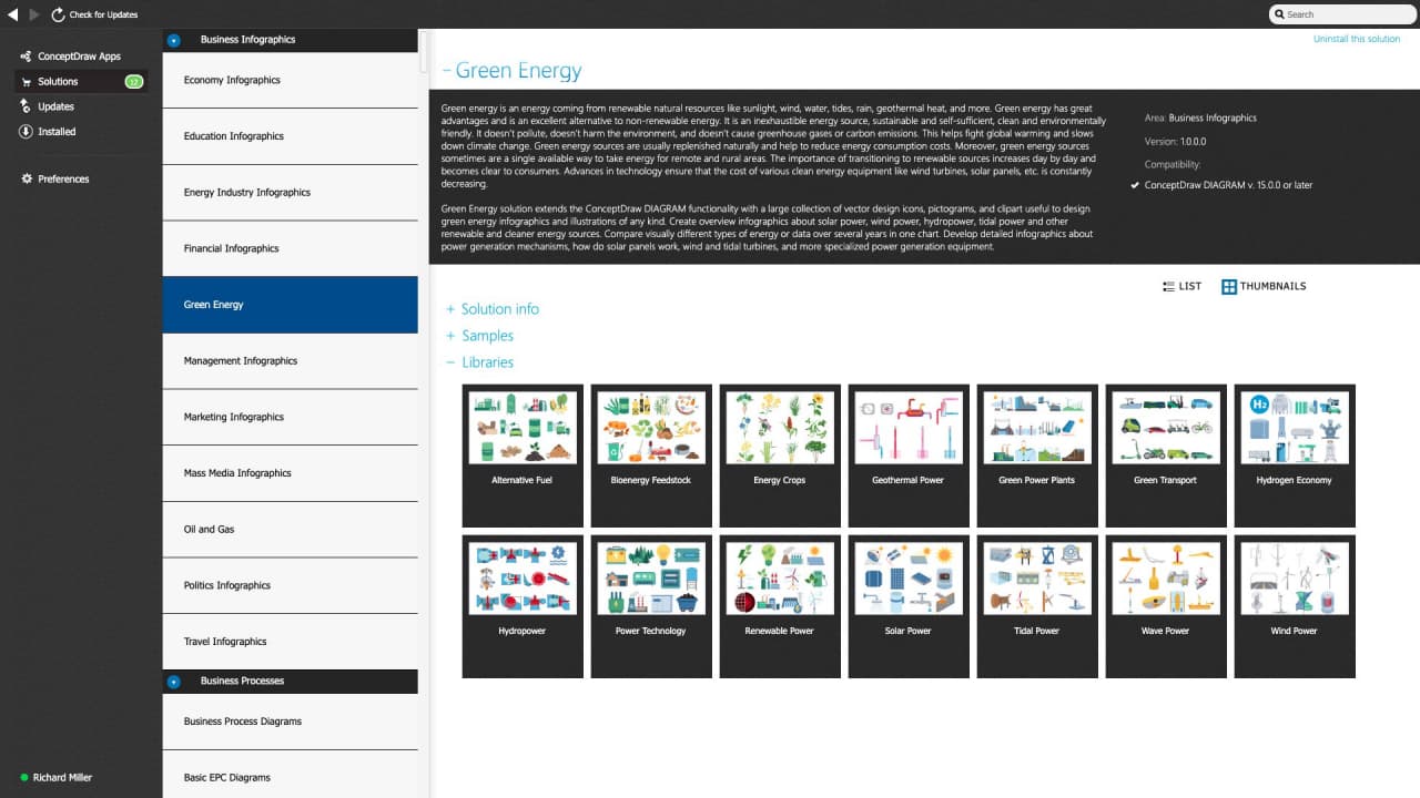
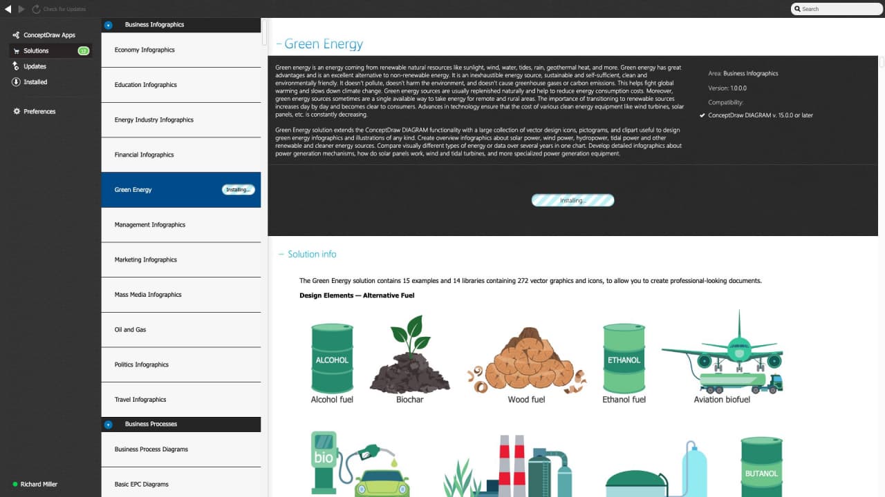
The Green Energy solution contains 15 examples and 14 libraries containing 272 vector graphics and icons, to allow you to create professional-looking documents.
Design Elements — Alternative Fuel

Design Elements — Bioenergy Feedstock

Design Elements — Energy Crops

Design Elements — Geothermal Power

Design Elements — Power Plants

Design Elements — Green Transport

Design Elements — Hydrogen Economy

Design Elements — Hydropower

Design Elements — Power Technology

Design Elements — Renewable Power

Design Elements — Solar Power

Design Elements — Tidal Power

Design Elements — Wave Power

Design Elements — Wind Power

Green Energy Examples
There are a few samples that you see on this page which were created in the ConceptDraw DIAGRAM application by using the Green Energy solution. Some of the solution's capabilities as well as the professional results which you can achieve are all demonstrated here on this page.
All source documents are vector graphic documents which are always available for modifying, reviewing and/or converting to many different formats, such as MS PowerPoint, PDF file, MS Visio, and many other graphic ones from the ConceptDraw Solution Park or ConceptDraw STORE. The Green Energy solution is available to all ConceptDraw DIAGRAM users to get installed and used while working in the ConceptDraw DIAGRAM diagramming and drawing software.
Example 1: Biofuel Types
This diagram was created in ConceptDraw DIAGRAM using the combination of libraries from the Green Energy solution. An experienced user spent 10 minutes creating this sample.
This sample shows a variety of biofuel types and classifies them by generation. Biofuel is a type of fuel produced from biomass at the application of special contemporary processes. Most biofuels are liquids and gaseous fuels. They include biodiesel, bioethanol, cellulosic biofuel, bio methanol, bio hydrogen, algal fuel, synthetic biofuels, and biogas. Biofuels are classified by generation and four generations are counted at the moment. First-generation biofuels are made from plants like crops, sugar cane, also starch, cellulose, animal manure, and food waste. The transesterification and yeast fermentation methods are used. Second-generation biofuels are produced from lignocellulose, woody biomass, straws, bagasse, perennial grasses, domestic, agricultural, municipal, and more waste. The third-generation biofuels are cleaner energy. They are made from microalgae and macroalgae, and their production is cheap. These biofuels are more energy intensive than biofuels of the first and second generation, biodegradable and fully renewable. Algae don't require special conditions and grows in the salt water of oceans and lakes, wastewater, etc. Cyanobacteria and algae are used for fourth-generation biofuels.

Example 2: Biohydrogen Production and Use
This diagram was created in ConceptDraw DIAGRAM using the combination of libraries from the Green Energy solution. An experienced user spent 10 minutes creating this sample.
This sample shows a general schematic of steps in biohydrogen production and use. All steps from feedstock production and processing to the transportation, storage, distribution, and end-use are presented. Biohydrogen is H2 biologically produced from certain kinds of biomass. It is a clean fuel, but there are some difficulties with the storage and transportation of a noncondensible gas. In addition, the yield of H2 is low and hydrogen-producing organisms are often poisoned by O2. Biohydrogen is mainly produced from algae and formed in a closed photobioreactor. There are two methods of biohydrogen production from biomass: thermochemical and biochemical. In normal conditions, algae produce oxygen using photosynthesis, but in conditions of sulfur lack, was noticed their trend to produce hydrogen. This capability is used in the biochemical production of biohydrogen. The thermochemical method involves heating the biomass without oxygen access to 500-800 °C, as a result, H2, CO, and CH4 are released.

Example 3: Concentrated Solar Power
This diagram was created in ConceptDraw DIAGRAM using the combination of libraries from the Green Energy solution. An experienced user spent 10 minutes creating this sample.
This green energy infographics sample is dedicated to concentrated solar power (CSP) used to produce electricity. The solar power is generated by CSP stations by means of using mirrors or lenses with tracking systems to concentrate a large area of sunlight onto a receiver. The concentrated light is used as a heat source for a power plant. CSP stations are similar to coal, gas, or geothermal power stations. They can include thermal energy storage and store energy in the form of sensible heat or latent heat. This enables electricity generation in any daytime or nighttime. Being converted to heat, the concentrated light powers a thermochemical reaction or drives a heat engine connected to an electrical power generator. This leads to electricity generation. A work of a parabolic trough system structure is based on the use of a linear parabolic reflector. It concentrates light onto a receiver located at the focal line of the reflector. A solar power tower includes dual-axis tracking reflectors, sunlight is concentrated on a central receiver atop a tower.

Example 4: From a Solar Cell to a PV System
This diagram was created in ConceptDraw DIAGRAM using the combination of libraries from the Green Energy solution. An experienced user spent 10 minutes creating this sample.
This sample shows the components of a photovoltaic (PV) system, step by step how it is constructed from the smallest segments to the whole system. PV systems range from small rooftop-mounted to large power stations, but all have a similar structure. A solar cell is the smallest part of a PV system. It is a special electrical device allowing absorbing sunlight energy and converting it directly into electricity by means of a photovoltaic effect. Typically, a single silicon solar cell can produce an open-circuit voltage of 0.5 to 0.6 volts. Electrical characteristics like current, voltage and resistance of a solar cell change when exposed to light. Multiple solar cells are placed in one plane and are connected to produce a solar module. A sheet of glass on the sun-facing side of a solar module allows protecting the semiconductor wafer at the simultaneous transmitting of light. In turn, several solar modules are united in a solar panel. A final PV system is formed from the array of solar panels. Visual infographics are incredibly useful to tell about how do solar panels work.

Example 5: Generation Capacity Factor
This diagram was created in ConceptDraw DIAGRAM using the combination of libraries from the Green Energy solution. An experienced user spent 10 minutes creating this sample.
This sample shows the distribution of capacity factors by energy source in the U.S. in 2019. The capacity factor equals the ratio of actual electrical energy output over a given period to the maximum possible electrical energy output over the same period. Both values from this ratio depend on a wide range of factors. The maximum possible energy output of some electricity-producing installation is its capacity during continuous operation at full power over a defined period. Commonly the capacity factor is calculated for a year, but sometimes it is required to track seasonal fluctuations and here the month values are useful. Typically, nuclear power plants are at the top of the power factor range of energy sources. The U.S. also had the highest capacity utilization rate in 2019 at 93.5%, while natural gas at 56.8%, coal at 47.5%, hydropower at 39.1%, wind power at 34. 8% and solar energy — 24.5%.

Example 6: Geothermal Power Stations
This diagram was created in ConceptDraw DIAGRAM using the combination of libraries from the Green Energy solution. An experienced user spent 15 minutes creating this sample.
This sample shows three kinds of geothermal power stations. The first is a dry steam power station. It generates electricity in a vapor-dominated hydrothermal system. Steam is injected directly from the subsurface wells and drives a turbine generator. In turn, wastewater from the condenser is injected back into the subsurface. The second is a flash steam power station including a hot-water hydrothermal system. Hot hydrothermal water is injected from the subsurface, partially flashed to steam, separated, and then used to drive a turbine generator. Wastewater from both separator and condenser is injected back into the subsurface, as well. Finally, a binary cycle power station is presented. It has two circuits. The first circuit uses hot water from a geothermal well and returns it to the underground reservoir at a lower temperature. The second one contains fluid with a low boiling point (isobutan). It is pumped at high pressure, vaporized, cold when passed through a turbine and cold air radiators, and returned back to the heat exchanger.

Example 7: Hybrid Power Systems
This diagram was created in ConceptDraw DIAGRAM using the combination of libraries from the Green Energy solution. An experienced user spent 5 minutes creating this sample.
This sample shows a hybrid power system. It is a complete electrical power supply system combining several energy sources. It includes wind and solar power systems. The use of different energy sources allows ensuring the non-intermittent delivery of electric power. Because the operating time and effectiveness of wind and solar sources differ according to the time of day and year. The hybrid power system includes three major elements: power sources, battery bank, and power management center. The power control center is the main governing body of the system. It regulates power production from each of the sources, controls its conversion and use. The power management center is connected to AC or DC load, controls the distribution of loads, and protects the battery from service extremes. The sources include wind turbines, solar PV systems, and generators (diesel, thermoelectric). The battery bank provides an autonomous operation for the system by means of compensating the difference between power production and use.

Example 8: Hydroelectric Dam
This diagram was created in ConceptDraw DIAGRAM using the combination of libraries from the Green Energy solution. An experienced user spent 15 minutes creating this sample.
This sample shows a cross-section schematic of a hydroelectric dam of a conventional type. Hydropower is a method of sustainable energy production having a relatively low cost and no waste. It has a low output level of greenhouse gases and that's why is really popular. Hydropower is produced in 150 countries and constitutes over 20% of the world's total electricity and 88% of all renewable electricity. Hydroelectric power plants produce electricity using falling or fast-running water. The amount of energy produced by the station can vary rapidly and significantly and exactly the use of a dam or reservoir allows making hydropower a flexible source of electricity. The main mechanism lies in converting the gravitational potential or kinetic energy of a water source. In conventional dam hydroelectric the potential energy of dammed water drives a water turbine and generator. Water from the reservoir is delivered through a large pipe to the turbine. The volume and difference in height between the source and the outlet of the water affect the amount of energy recovered.

Example 9: Hydrogen Color Codes
This diagram was created in ConceptDraw DIAGRAM using the combination of libraries from the Green Energy solution. An experienced user spent 15 minutes creating this sample.
This sample shows the hydrogen production from renewable and non-renewable sources. Several types of hydrogen are differed according to the production method. The more carbon oxides are released during the production, the less environmentally friendly hydrogen is. Each type has its own hydrogen color code. Green hydrogen is the most environmentally friendly, it is obtained by electrolysis. All that is needed for this is only water, electrolyzer, and electricity. There are no CO2 emissions at the use of electricity from renewable sources. Gray hydrogen is produced by steam methane reforming consuming natural gas with releasing of carbon dioxide. Blue hydrogen is also produced by steam methane reforming, but carbon is captured and stored. This reduces emissions at the increasing the production cost. Brown hydrogen uses brown coal as a raw material. With the help of the gasification of brown coal, synthesis gas is formed. It is a mixture of CO2, CO, hydrogen, methane, ethylene, and other gases in small quantities. This production is the most polluting.

Example 10: Renewable Energy to Electricity or Hydrogen
This diagram was created in ConceptDraw DIAGRAM using the combination of libraries from the Green Energy solution. An experienced user spent 15 minutes creating this sample.
This sample shows the ways of producing electricity and hydrogen from ecology-friendly renewable energy sources. Renewable energy resources allow gaining energy from wind, sunlight, geothermal heat, tides, and more natural phenomena. They occupy wide geographical areas and have great potential. Water electrolysis is a major way to produce hydrogen, store the excess energy as hydrogen for further transportation and industrial use. Hydrogen and oxygen are released as byproducts in the electrolysis of water in an electrolyzer when electrical energy is converted into chemical energy. Two types of electrolyzers are applied at the moment: alkaline and proton exchange membrane (PEM). And one more type — solid-oxide-based high-temperature electrolyzers are in development. The main task of today's research is to lower the cost of electrolyzers with simultaneous increasing their efficiency, durability, and safety. The electrical energy is later recovered as a result of hydrogen reacting with oxygen in fuel cell vehicles and combustion engines.

Example 11: Solar Power
This diagram was created in ConceptDraw DIAGRAM using the combination of libraries from the Green Energy solution. An experienced user spent 5 minutes creating this sample.
This sample shows how solar PV systems work. Solar energy, a form of alternative energy, relies on the use of sunlight to generate electricity. The use of a renewable source makes solar energy environmentally friendly, without harmful waste. The solar energy industry actively develops and volumes of use of solar PV increase year by year. The technologies are improved and their cost decreases. Solar PV systems convert the energy from sunlight into an electric current using photovoltaic (PV) cells and the photovoltaic effect. Multiple PV cells or solar cells are connected in a solar module. In turn, several modules form a solar panel. Multiple panels wired together build a solar array producing direct current (DC) power. It fluctuates with the sunlight's intensity. Then the arrays are tied to an inverter ensuring conversion of direct current to certain desired voltages or alternating current (AC). The electric current of suitable voltage is distributed through electrical grids to residential premises and enterprises.

Example 12: Tidal Power
This diagram was created in ConceptDraw DIAGRAM using the combination of libraries from the Green Energy solution. An experienced user spent 10 minutes creating this sample.
This sample is dedicated to tidal power and methods of its generating. Tidal power or tidal energy is a kind of energy gaining by means of converting energy from moving water, tides into electricity using different methods. It is a sufficiently sustainable kind of energy with great future potential because tides are more predictable than wind and sun. In the last decades, it actively develops and a lot of improvements in the mechanism and construction of turbines were made. However, this energy has a high cost of production and complexities in taking tidal energy related to flow velocities and limited availability of sites with sufficiently high tidal ranges. The most common methods of tidal power generation include the use of a tidal stream power, a tidal barrage power and dynamic tidal power using a DTP dam, turbine, installation. Tidal stream generators use the kinetic energy of the tide to power the turbines. Tidal barrages use the potential energy of the difference in the heights of the low tide and flow. In terms of dynamic tidal force, very long dams are built on the seashore or ocean, and a significant difference in water level results in strong tidal currents.

Example 13: Wave Energy Concepts
This diagram was created in ConceptDraw DIAGRAM using the combination of libraries from the Green Energy solution. An experienced user spent 10 minutes creating this sample.
This sample is dedicated to the wave power that is the capture of energy of wind waves by wave energy converter (WEC) with a goal of electricity generation. At the moment, wave-power generation is not used as widely as solar energy, tidal energy, and hydropower. Wave power devices are classified according to location, power take-off system, and the method used to capture or harness wave energy. There are used absolutely different concepts and mechanisms to generate wave energy: point absorber, oscillating wave surge converter, oscillating water column, surface attenuator, overtopping device, submerged pressure differential, and floating in-air converters. Point absorber buoy floats on the surface of the water and uses the rise and fall of swells to generate electricity. The surface attenuator has several interconnecting floating segments; the protrusions create a bending motion driving the hydraulic pumps to generate electricity. Oscillating water columns contain built-in air chambers, and submersible differential pressure transmitters use membranes to extract wave energy. The shut-off devices use the speed of the wave and the reservoir fills to a higher water level than the surrounding ocean.

Example 14: Wind Turbine Design
This diagram was created in ConceptDraw DIAGRAM using the combination of libraries from the Green Energy solution. An experienced user spent 10 minutes creating this sample.
This sample shows a design of a wind turbine. The wind turbine design is the process of defining the best form and configuration to extract energy from the wind the most efficiently. A form and configuration of a wind turbine are chosen not random. The wind turbine includes the components capturing the wind's energy, pointing the turbine into the wind, and converting mechanical rotation into electrical power. It also includes the systems responsible for the start, stop, and control of the turbine. Among the main components are a foundation, connection to the electric grid, tower, access ladder, wind orientation control, nacelle, generator, anemometer, brake, gearbox, rotor blade, blade pitch control, and rotor hub. The required aerodynamic performance defines the shape and dimension of the blades, vortex generators control their lift characteristics. The centrifugal force on the blades increases as the square of the rotation speed, that's why the rotation speed needs to be controlled. A control system includes sensors and actuators to control and manipulate energy capture.

Example 15: Wind Turbine Energy Distribution
This diagram was created in ConceptDraw DIAGRAM using the combination of libraries from the Green Energy solution. An experienced user spent 5 minutes creating this sample.
Wind turbines are the source of renewable energy widely used in many countries all over the world. They convert the wind's kinetic energy into electrical energy. Wind turbines help to lower energy costs, reduce reliance on fossil fuels, and decrease gas emissions and pollution environment. The turbines of different size, shape, number of blades, material, axis of rotation (horizontal or vertical), and pitch of the screw are constructed and used. Large wind turbines are used on an industrial scale and installed by the state or large energy corporations. The smaller ones are used to power small devices like traffic warning signs or provide auxiliary power for boats, etc. This sample shows a wind turbine energy distribution. The wind spins the rotor, the generated electricity is supplied through the charge controller to the batteries. The power inverter converts the voltage at the battery contacts into usable one. The electrical grids are connected with power distribution units, from where energy is distributed to the end consumer.

Inside

What I Need to Get Started
After ConceptDraw DIAGRAM is installed, the Green Energy solution can be purchased either from the Business Infographics area of ConceptDraw STORE itself or from our online store. Thus, you will be able to use the Green Energy solution straight after.
How to install
First of all, make sure that both ConceptDraw STORE and ConceptDraw DIAGRAM applications are downloaded and installed on your computer. Next, install the Green Energy solution from the ConceptDraw STORE to use it in the ConceptDraw DIAGRAM application.
Start using
Start using the Green Energy solution to make the professionally looking illustrations by adding the design elements taken from the stencil libraries and editing the pre-made examples that can be found there.