- Electric and Telecom Plans Free
- Fire and Emergency Plans Free
- Floor Plans Free
- Plant Layout Plans Free
- School and Training Plans Free
- Seating Plans Free
- Security and Access Plans Free
- Site Plans Free
- Sport Field Plans Free
- Business Process Diagrams Free
- Business Process Mapping Free
- Classic Business Process Modeling Free
- Cross-Functional Flowcharts Free
- Event-driven Process Chain Diagrams Free
- IDEF Business Process Diagrams Free
- Logistics Flow Charts Free
- Workflow Diagrams Free
- ConceptDraw Dashboard for Facebook Free
- Mind Map Exchange Free
- MindTweet Free
- Note Exchange Free
- Project Exchange Free
- Social Media Response Free
- Active Directory Diagrams Free
- AWS Architecture Diagrams Free
- Azure Architecture Free
- Cisco Network Diagrams Free
- Cisco Networking Free
- Cloud Computing Diagrams Free
- Computer Network Diagrams Free
- Google Cloud Platform Free
- Interactive Voice Response Diagrams Free
- Network Layout Floor Plans Free
- Network Security Diagrams Free
- Rack Diagrams Free
- Telecommunication Network Diagrams Free
- Vehicular Networking Free
- Wireless Networks Free
- Comparison Dashboard Free
- Composition Dashboard Free
- Correlation Dashboard Free
- Frequency Distribution Dashboard Free
- Meter Dashboard Free
- Spatial Dashboard Free
- Status Dashboard Free
- Time Series Dashboard Free
- Basic Circle-Spoke Diagrams Free
- Basic Circular Arrows Diagrams Free
- Basic Venn Diagrams Free
- Block Diagrams Free
- Concept Maps Free
- Family Tree Free
- Flowcharts Free
- Basic Area Charts Free
- Basic Bar Graphs Free
- Basic Divided Bar Diagrams Free
- Basic Histograms Free
- Basic Line Graphs Free
- Basic Picture Graphs Free
- Basic Pie Charts Free
- Basic Scatter Diagrams Free
- Aerospace and Transport Free
- Artwork Free
- Audio, Video, Media Free
- Business and Finance Free
- Computers and Communications Free
- Holiday Free
- Manufacturing and Maintenance Free
- Nature Free
- People Free
- Presentation Clipart Free
- Safety and Security Free
- Analog Electronics Free
- Audio and Video Connectors Free
- Basic Circuit Diagrams Free
- Chemical and Process Engineering Free
- Digital Electronics Free
- Electrical Engineering Free
- Electron Tube Circuits Free
- Electronic Block Diagrams Free
- Fault Tree Analysis Diagrams Free
- GHS Hazard Pictograms Free
- Home Automation and Wiring Free
- Mechanical Engineering Free
- One-line Diagrams Free
- Power Сircuits Free
- Specification and Description Language (SDL) Free
- Telecom and AV Circuits Free
- Transport Hazard Pictograms Free
- Data-driven Infographics Free
- Pictorial Infographics Free
- Spatial Infographics Free
- Typography Infographics Free
- Calendars Free
- Decision Making Free
- Enterprise Architecture Diagrams Free
- Fishbone Diagrams Free
- Organizational Charts Free
- Plan-Do-Check-Act (PDCA) Free
- Seven Management and Planning Tools Free
- SWOT and TOWS Matrix Diagrams Free
- Timeline Diagrams Free
- Australia Map Free
- Continent Maps Free
- Directional Maps Free
- Germany Map Free
- Metro Map Free
- UK Map Free
- USA Maps Free
- Customer Journey Mapping Free
- Marketing Diagrams Free
- Matrices Free
- Pyramid Diagrams Free
- Sales Dashboard Free
- Sales Flowcharts Free
- Target and Circular Diagrams Free
- Cash Flow Reports Free
- Current Activities Reports Free
- Custom Excel Report Free
- Knowledge Reports Free
- MINDMAP Reports Free
- Overview Reports Free
- PM Agile Free
- PM Dashboards Free
- PM Docs Free
- PM Easy Free
- PM Meetings Free
- PM Planning Free
- PM Presentations Free
- PM Response Free
- Resource Usage Reports Free
- Visual Reports Free
- House of Quality Free
- Quality Mind Map Free
- Total Quality Management TQM Diagrams Free
- Value Stream Mapping Free
- Astronomy Free
- Biology Free
- Chemistry Free
- Language Learning Free
- Mathematics Free
- Physics Free
- Piano Sheet Music Free
- Android User Interface Free
- Class Hierarchy Tree Free
- Data Flow Diagrams (DFD) Free
- DOM Tree Free
- Entity-Relationship Diagram (ERD) Free
- EXPRESS-G data Modeling Diagram Free
- IDEF0 Diagrams Free
- iPhone User Interface Free
- Jackson Structured Programming (JSP) Diagrams Free
- macOS User Interface Free
- Object-Role Modeling (ORM) Diagrams Free
- Rapid UML Free
- SYSML Free
- Website Wireframe Free
- Windows 10 User Interface Free
IDEF0 Diagrams
IDEF0 is known to be an acronym for “Icam DEFinition for Function Modeling”, where “ICAM” is also an acronym meaning the “Integrated Computer Aided Manufacturing”. Being a function modeling methodology for describing multiple manufacturing functions, it offers a functional modeling language for the analysis, re-engineering, integration and development of different information systems, business processes and software engineering analysis.
Being a member of the IDEF modeling languages family in such sphere of business as software engineering, IDEF0 is built on the functional modeling language – SADT (Structured Analysis and Design Technique). The so-called “IDEF0 Functional Modeling method” is known to be designed for being able to model the needed actions, activities and decisions within some organization. Being derived from the SADT, IDEF0 was originally expected to assist in organizing system analysis as well as to promote the effective communication between the customer and the analyst.
IDEF0 may be also used for modeling both automated and non-automated systems, being applied in the new systems for defining the requirements and specifying the functions. It may also allow designing an implementation that performs the functions and meets the needed requirements. For analyzing the functions, the system performs and for recording the mechanisms by which these are done, IDEF0 may be applied to any system. As a result, a model that consists of a hierarchical series of diagrams, glossary and text can be created.
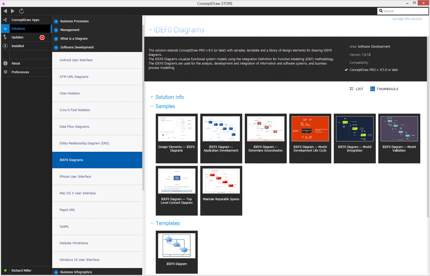
To make the needed model, the ConceptDraw DIAGRAM charting and drawing software can be created. Having the IDEF0 Diagrams solution as well may lead to getting the professionally-looking drawings based on the pre-made samples and templates from solution. There is also a stencil library with the IDEF0-related design elements that can be taken from this solution in order to draw the IDEF0 diagrams.
The IDEF0 Diagrams solution can be used by many IT specialists for creating the needed IDEF0 Diagrams that can be later used for the analysis, integration, and development of information as well as numeral software systems, and for business process modeling.
-
Install this solution Free -
What I need to get started -
Solution Requirements - This solution requires the following products to be installed:
ConceptDraw DIAGRAM v18 - This solution requires the following products to be installed:
-
Compatibility - Sonoma (14), Sonoma (15)
MS Windows 10, 11 - Sonoma (14), Sonoma (15)
-
Support for this Solution -
Helpdesk
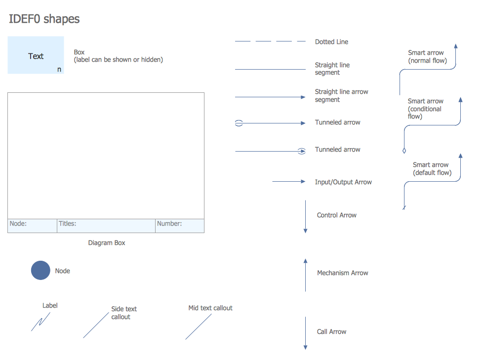
There is 1 library containing 18 vector shapes in the IDEF0 Diagrams solution.
Design Elements — IDEF0 Diagrams
IDEF0 Diagrams Examples
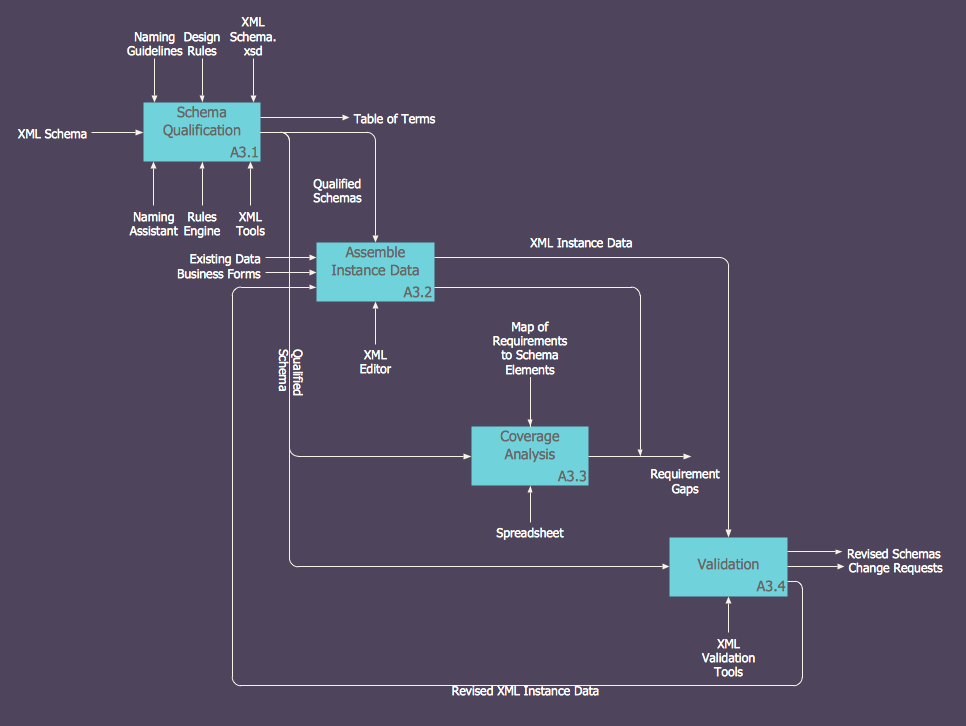
There are a few samples that you see on this page which were created in the ConceptDraw DIAGRAM application by using the IDEF0 Diagrams solution. Some of the solution's capabilities as well as the professional results which you can achieve are all demonstrated here on this page.
All source documents are vector graphic documents which are always available for modifying, reviewing and/or converting to many different formats, such as MS PowerPoint, PDF file, MS Visio, and many other graphic ones from the ConceptDraw Solution Park or ConceptDraw STORE. The IDEF0 Diagrams solution is available to all ConceptDraw DIAGRAM users to get installed and used while working in the ConceptDraw DIAGRAM diagramming and drawing software.
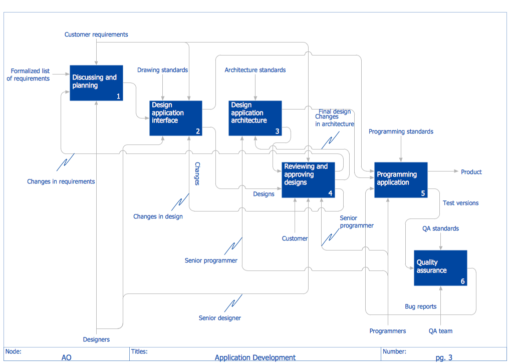
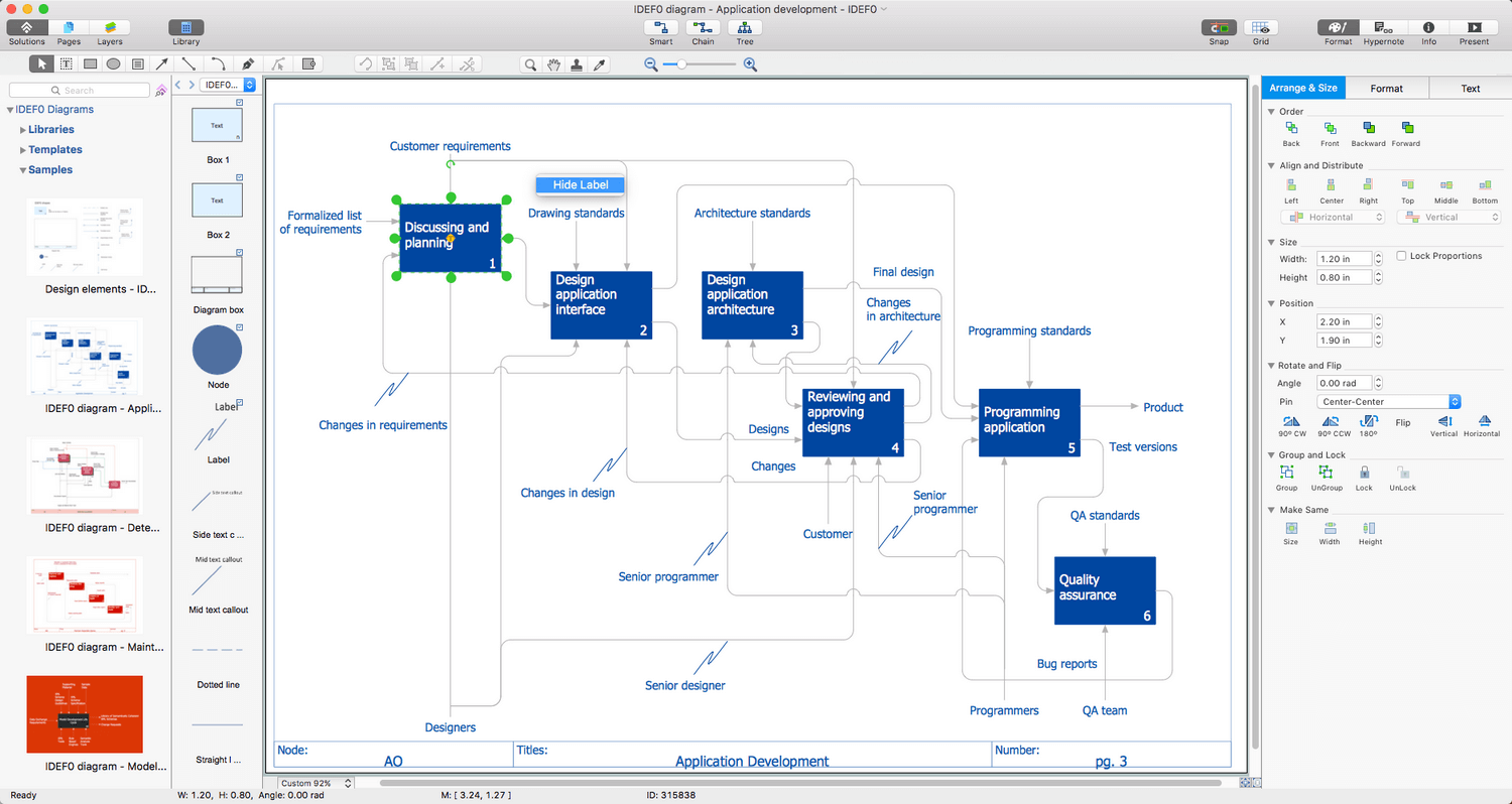
Example 1: IDEF0 Diagram — Application Development
This diagram was created in ConceptDraw DIAGRAM using the IDEF0 Diagrams Library from the IDEF0 Diagrams Solution. An experienced user spent 20 minutes creating this sample.
This IDEF0 diagram shows a detailed description of an application-development process. The steps of this process are represented by blocks which are visually arranged according to their logical levels.
Example 2: IDEF0 Diagram — Model Integration
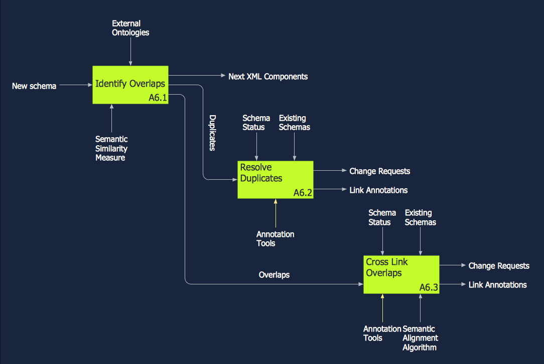
This diagram was created in ConceptDraw DIAGRAM using the IDEF0 Diagrams Library from the IDEF0 Diagrams Solution. An experienced user spent 15 minutes creating this sample.
This sample shows an IDEF0 diagram representing the processes that comprise model integration. Note that each process has a unique identification number. The interactions between processes are represented by arrows which connect outputs of one process with the inputs of another.
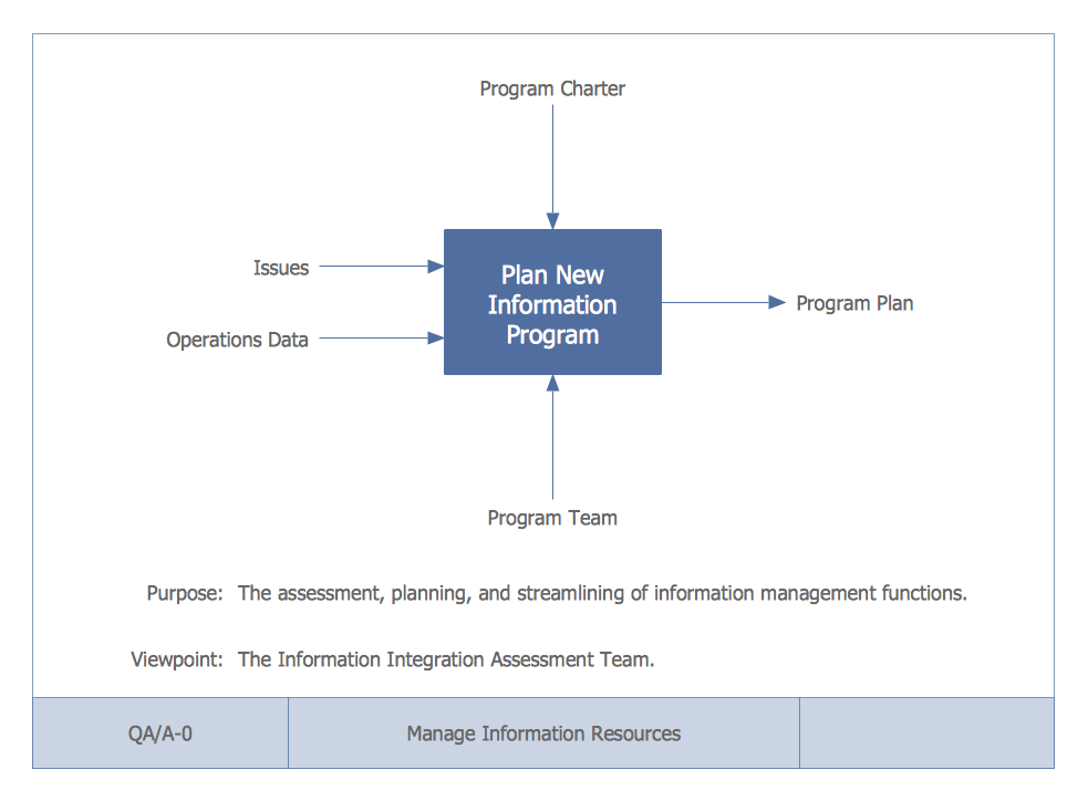
Example 3: IDEF0 Diagram — Top Level Context Diagram
This diagram was created in ConceptDraw DIAGRAM using the IDEF0 Diagrams Library from the IDEF0 Diagrams Solution. An experienced user spent 20 minutes creating this sample.
This sample demonstrates a top level context diagram for an information system management process. The main function of this IDEF0 Diagram is highlighted to attract attention.
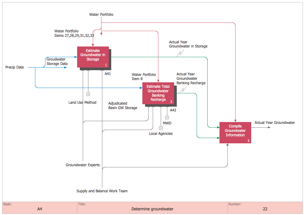
Example 4: IDEF0 Diagram — Determine Groundwater
This diagram was created in ConceptDraw DIAGRAM using the IDEF0 Diagrams Library from the IDEF0 Diagrams Solution. An experienced user spent 20 minutes creating this sample.
This IDEF0 diagram demonstrates the process of assessing groundwater. Arrange the blocks an equal distance from each other and highlight them with color to make the diagram stylish, and easy to both read and understand.
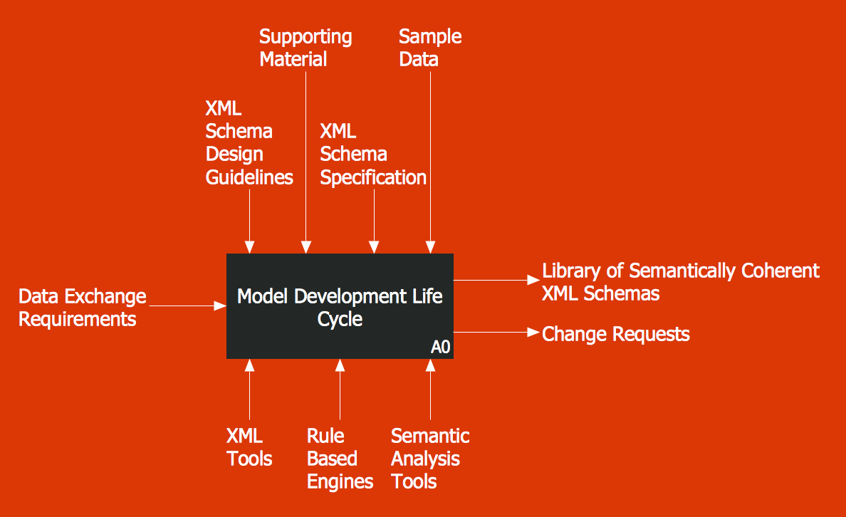
Example 5: IDEF0 Diagram — Model Development Life Cycle
This diagram was created in ConceptDraw DIAGRAM using the IDEF0 Diagrams Library from the IDEF0 Diagrams Solution. An experienced user spent 10 minutes creating this sample.
This IDEF0 diagram shows a model development life cycle. The bright colors make this diagram attractive and ready for use in different presentations, conferences, and publications.
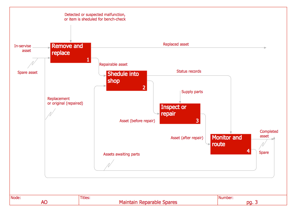
Example 6: Maintain Reparable Spares
This diagram was created in ConceptDraw DIAGRAM using the IDEF0 Diagrams Library from the IDEF0 Diagrams Solution. An experienced user spent 10 minutes creating this sample.
Example 7: IDEF0 Diagrams — Model Validation
This diagram was created in ConceptDraw DIAGRAM using the IDEF0 Diagrams Library from the IDEF0 Diagrams Solution. An experienced user spent 15 minutes creating this sample.
Inside
What I Need to Get Started
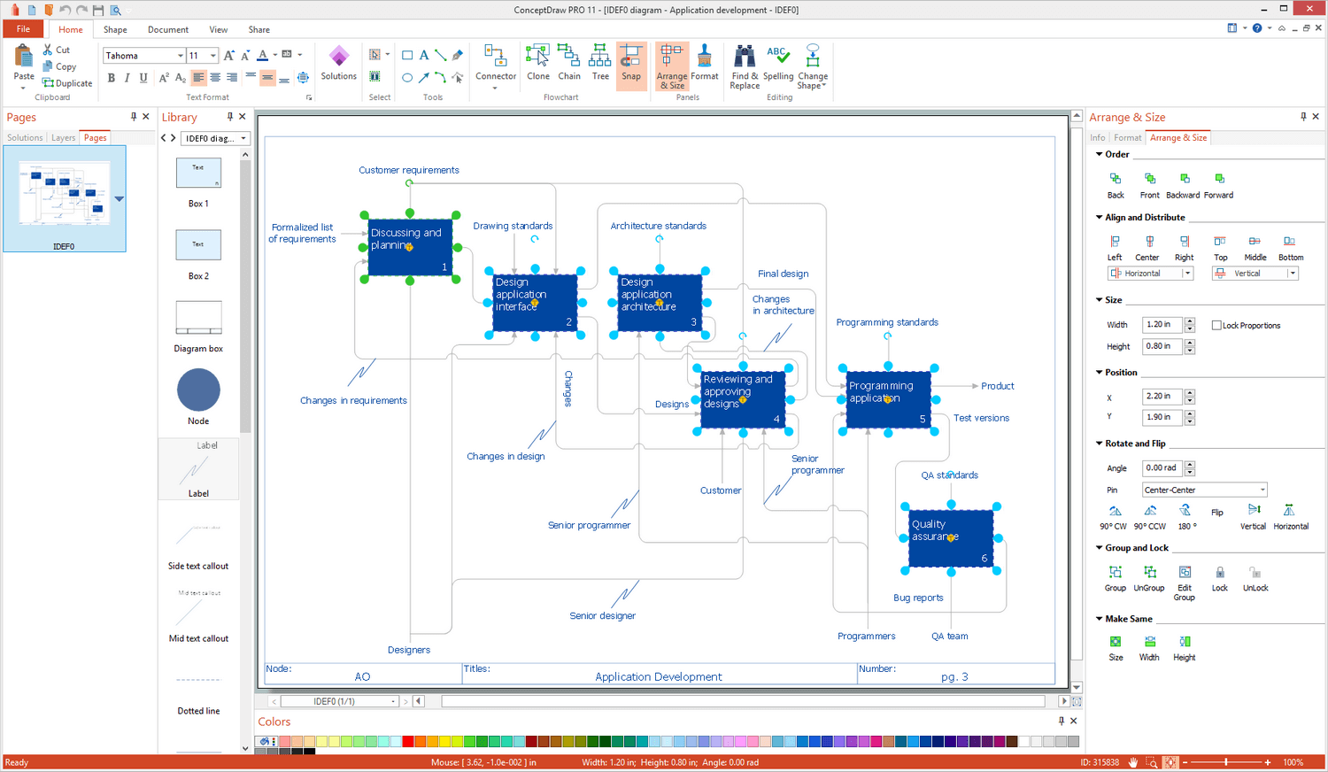
Both ConceptDraw DIAGRAM diagramming and drawing software and the IDEF0 Diagrams solution can help creating the software engineering diagrams you need. The IDEF0 Diagrams solution can be found in the Software Development area of ConceptDraw STORE application that can be downloaded from this site. Make sure that both ConceptDraw DIAGRAM and ConceptDraw STORE applications are installed on your computer before you get started.
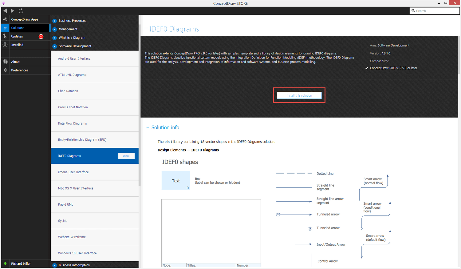
How to install
After ConceptDraw STORE and ConceptDraw DIAGRAM are downloaded and installed, you can install the IDEF0 Diagrams solution from the ConceptDraw STORE.
Start Using
To make sure that you are doing it all right, use the pre-designed symbols from the stencil libraries from the solution to make your drawings look smart and professional. Also, the pre-made examples from this solution can be used as drafts so your own drawings can be based on them. Using the samples, you can always change their structures, colors and data.
