- Electric and Telecom Plans Free
- Fire and Emergency Plans Free
- Floor Plans Free
- Plant Layout Plans Free
- School and Training Plans Free
- Seating Plans Free
- Security and Access Plans Free
- Site Plans Free
- Sport Field Plans Free
- Business Process Diagrams Free
- Business Process Mapping Free
- Classic Business Process Modeling Free
- Cross-Functional Flowcharts Free
- Event-driven Process Chain Diagrams Free
- IDEF Business Process Diagrams Free
- Logistics Flow Charts Free
- Workflow Diagrams Free
- ConceptDraw Dashboard for Facebook Free
- Mind Map Exchange Free
- MindTweet Free
- Note Exchange Free
- Project Exchange Free
- Social Media Response Free
- Active Directory Diagrams Free
- AWS Architecture Diagrams Free
- Azure Architecture Free
- Cisco Network Diagrams Free
- Cisco Networking Free
- Cloud Computing Diagrams Free
- Computer Network Diagrams Free
- Google Cloud Platform Free
- Interactive Voice Response Diagrams Free
- Network Layout Floor Plans Free
- Network Security Diagrams Free
- Rack Diagrams Free
- Telecommunication Network Diagrams Free
- Vehicular Networking Free
- Wireless Networks Free
- Comparison Dashboard Free
- Composition Dashboard Free
- Correlation Dashboard Free
- Frequency Distribution Dashboard Free
- Meter Dashboard Free
- Spatial Dashboard Free
- Status Dashboard Free
- Time Series Dashboard Free
- Basic Circle-Spoke Diagrams Free
- Basic Circular Arrows Diagrams Free
- Basic Venn Diagrams Free
- Block Diagrams Free
- Concept Maps Free
- Family Tree Free
- Flowcharts Free
- Basic Area Charts Free
- Basic Bar Graphs Free
- Basic Divided Bar Diagrams Free
- Basic Histograms Free
- Basic Line Graphs Free
- Basic Picture Graphs Free
- Basic Pie Charts Free
- Basic Scatter Diagrams Free
- Aerospace and Transport Free
- Artwork Free
- Audio, Video, Media Free
- Business and Finance Free
- Computers and Communications Free
- Holiday Free
- Manufacturing and Maintenance Free
- Nature Free
- People Free
- Presentation Clipart Free
- Safety and Security Free
- Analog Electronics Free
- Audio and Video Connectors Free
- Basic Circuit Diagrams Free
- Chemical and Process Engineering Free
- Digital Electronics Free
- Electrical Engineering Free
- Electron Tube Circuits Free
- Electronic Block Diagrams Free
- Fault Tree Analysis Diagrams Free
- GHS Hazard Pictograms Free
- Home Automation and Wiring Free
- Mechanical Engineering Free
- One-line Diagrams Free
- Power Сircuits Free
- Specification and Description Language (SDL) Free
- Telecom and AV Circuits Free
- Transport Hazard Pictograms Free
- Data-driven Infographics Free
- Pictorial Infographics Free
- Spatial Infographics Free
- Typography Infographics Free
- Calendars Free
- Decision Making Free
- Enterprise Architecture Diagrams Free
- Fishbone Diagrams Free
- Organizational Charts Free
- Plan-Do-Check-Act (PDCA) Free
- Seven Management and Planning Tools Free
- SWOT and TOWS Matrix Diagrams Free
- Timeline Diagrams Free
- Australia Map Free
- Continent Maps Free
- Directional Maps Free
- Germany Map Free
- Metro Map Free
- UK Map Free
- USA Maps Free
- Customer Journey Mapping Free
- Marketing Diagrams Free
- Matrices Free
- Pyramid Diagrams Free
- Sales Dashboard Free
- Sales Flowcharts Free
- Target and Circular Diagrams Free
- Cash Flow Reports Free
- Current Activities Reports Free
- Custom Excel Report Free
- Knowledge Reports Free
- MINDMAP Reports Free
- Overview Reports Free
- PM Agile Free
- PM Dashboards Free
- PM Docs Free
- PM Easy Free
- PM Meetings Free
- PM Planning Free
- PM Presentations Free
- PM Response Free
- Resource Usage Reports Free
- Visual Reports Free
- House of Quality Free
- Quality Mind Map Free
- Total Quality Management TQM Diagrams Free
- Value Stream Mapping Free
- Astronomy Free
- Biology Free
- Chemistry Free
- Language Learning Free
- Mathematics Free
- Physics Free
- Piano Sheet Music Free
- Android User Interface Free
- Class Hierarchy Tree Free
- Data Flow Diagrams (DFD) Free
- DOM Tree Free
- Entity-Relationship Diagram (ERD) Free
- EXPRESS-G data Modeling Diagram Free
- IDEF0 Diagrams Free
- iPhone User Interface Free
- Jackson Structured Programming (JSP) Diagrams Free
- macOS User Interface Free
- Object-Role Modeling (ORM) Diagrams Free
- Rapid UML Free
- SYSML Free
- Website Wireframe Free
- Windows 10 User Interface Free
HVAC Plans
HVAC is the abbreviation for heating, ventilation and air conditioning. It is the technology of both indoor and vehicular environmental comfort, which goal is providing maximum thermal comfort as well as the proper indoor air quality.
Refrigeration may be sometimes added to the field's abbreviation as either HVACR or HVAC&R. Thus, HVAC is one of the most important parts of the residential structures. The structures may be the single-family homes, hotels, senior living facilities, apartment buildings, office and industrial buildings. The buildings such as hospitals and skyscrapers, or submarines and ships as well as in the marine environments, where safe and healthy building conditions are known to be regulated taking into consideration both humidity and temperature, using fresh air from outdoors, HVAC system can be also involved.
Ventilation or ventilating is also a part of HVAC, being the process of either replacing or exchanging the air in any space in order to provide high indoor air quality. The last mentioned involves temperature control, removal of odours, moisture, smoke, heat, airborne bacteria, dust, carbon dioxide, and other gases, as well as oxygen replenishment. Ventilation is what removes the excessive moisture and the unpleasant smells introducing the outside air and keeping the interior building air circulating. It prevents the stagnation of the interior air, including both the circulation of air within the building and the exchange of air to the outside.
HVAC Plans solution is what extends the ConceptDraw DIAGRAM diagramming and drawing software with the pre-made examples and templates of HVAC blueprints, HVAC sketches, HVAC plans and designs, including the HVAC floor plans, HVAC business plans, HVAC marketing plans and plans of the arrangement of varied HVAC equipment. There are also the vector stencil libraries full of the design elements for drawing any needed HVAC plans by mechanicals, engineers, technologists, interior designers, architects, telecommunications managers, builders and other technicians.
-
Buy this solution $49 -
Solution Requirements - This solution requires the following products to be installed:
ConceptDraw DIAGRAM v18 - This solution requires the following products to be installed:
-
Compatibility - Sonoma (14), Sonoma (15)
MS Windows 10, 11 - Sonoma (14), Sonoma (15)
-
Support for this Solution -
Helpdesk
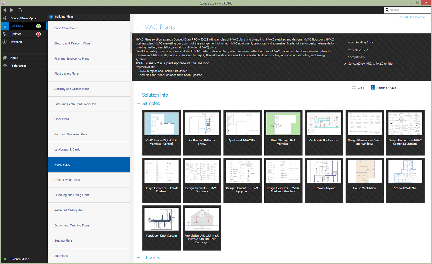
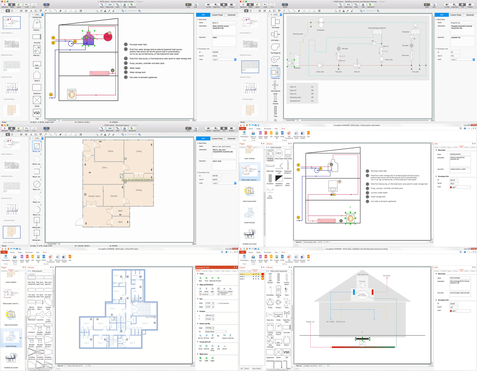
The HVAC Plans solution contains 16 examples and 7 libraries containing 332 vector graphics and icons.
Design Elements — HVAC Controls
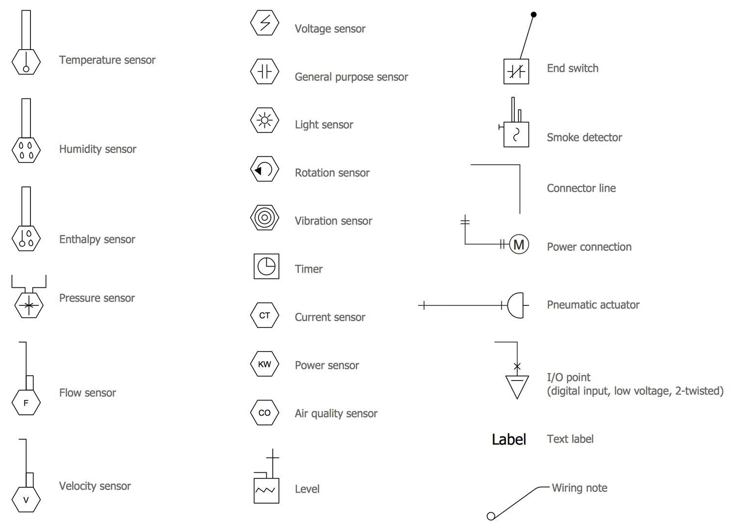
Design Elements — HVAC Controls Equipment
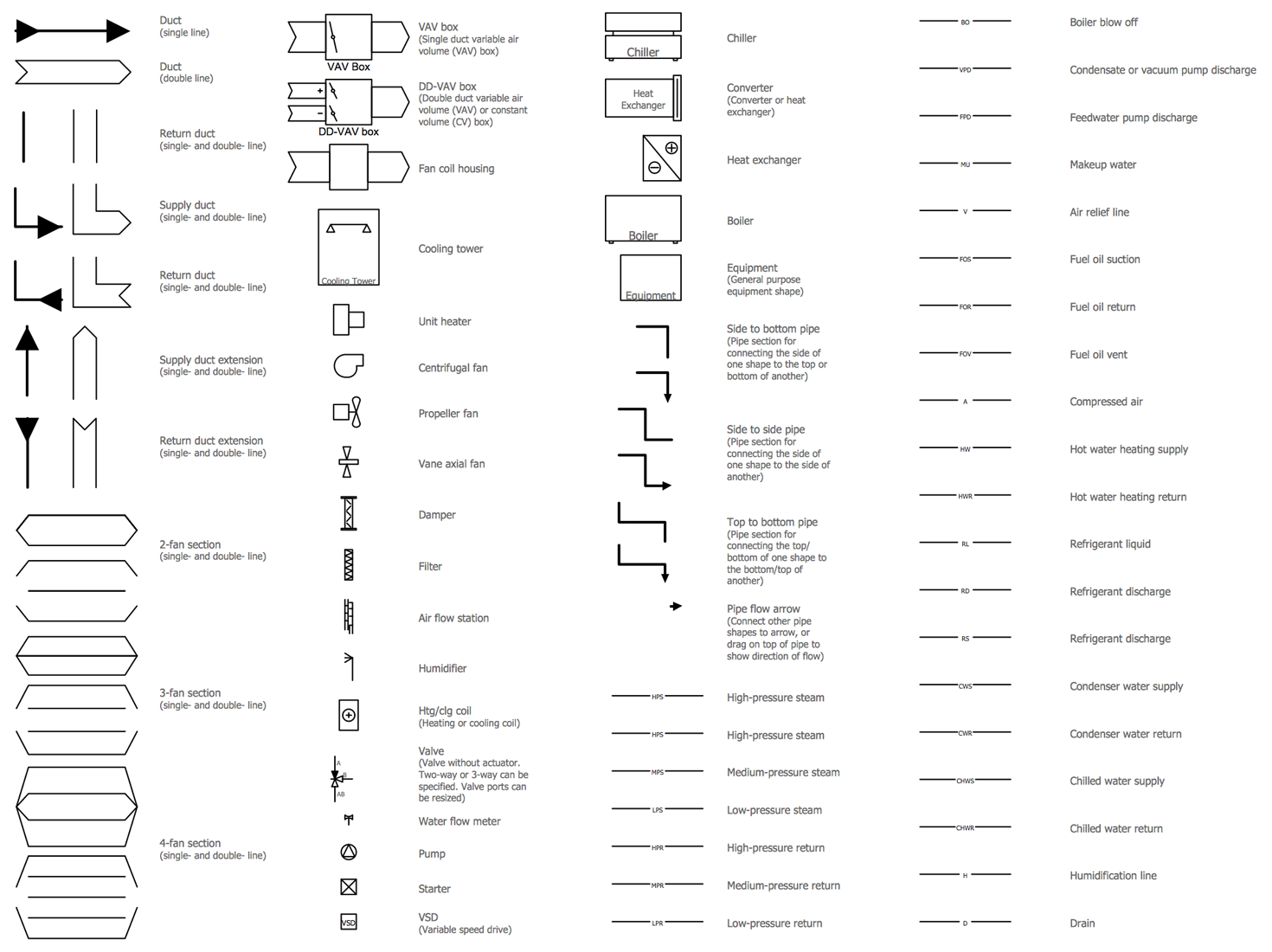
Design Elements — HVAC Ductwork
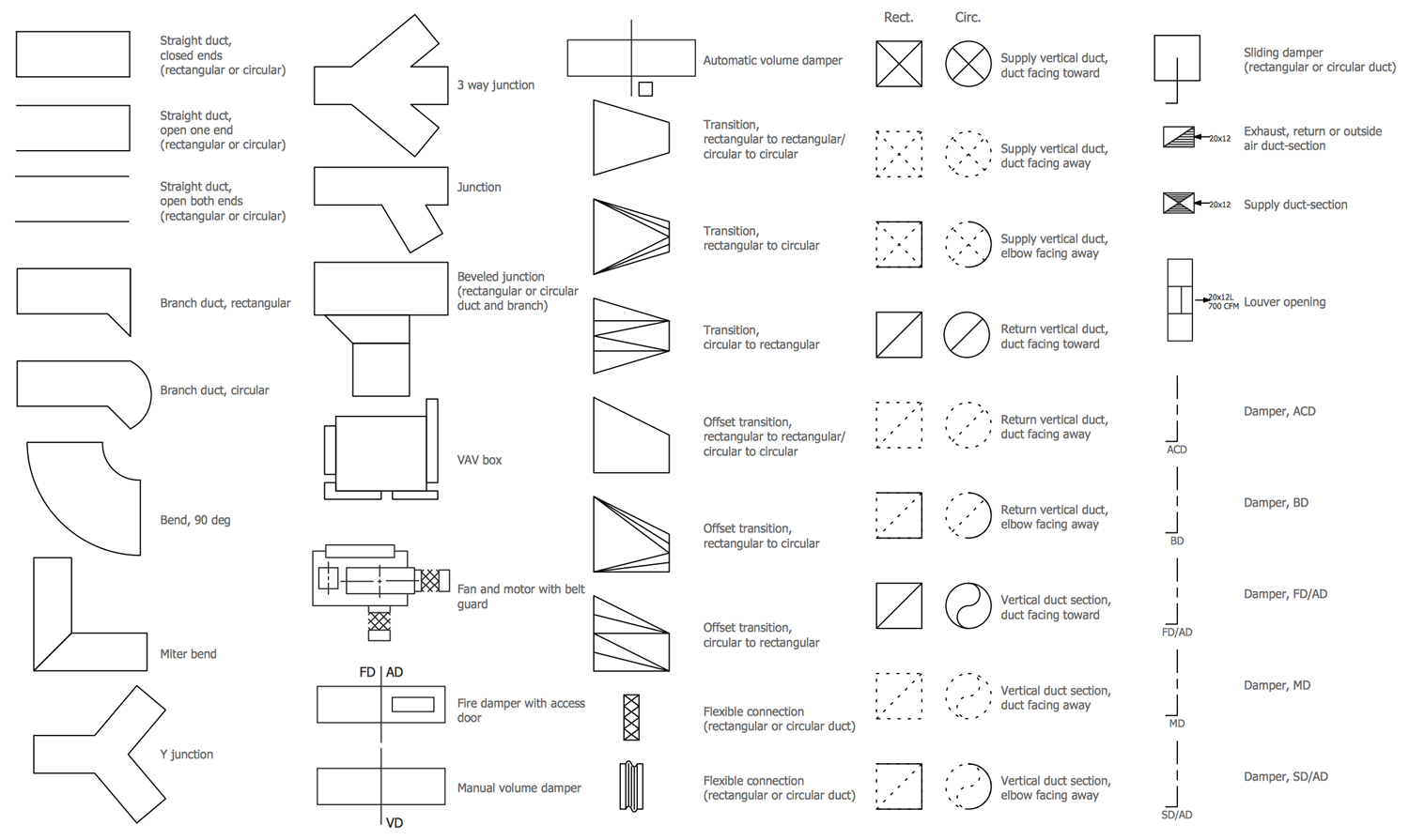
Design Elements — HVAC Equipment
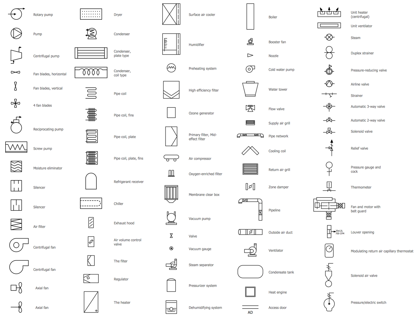
Design Elements — Air Conditioning
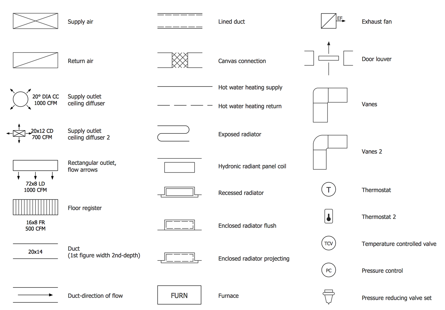
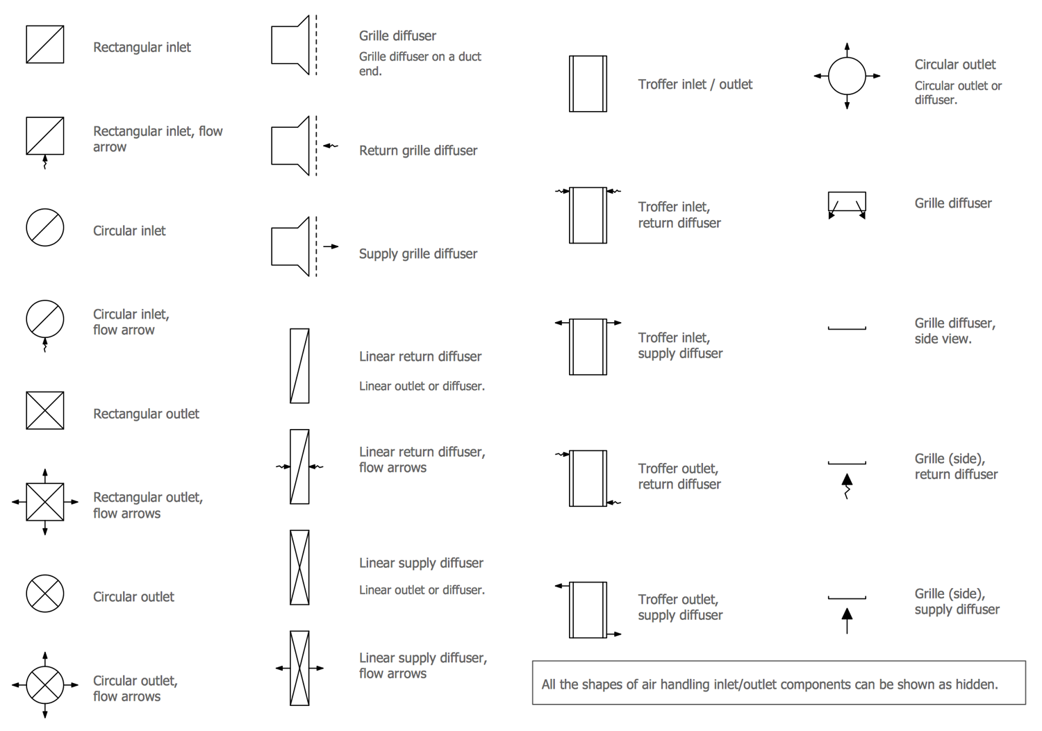
Design Elements — Registers Drills and Diffusers
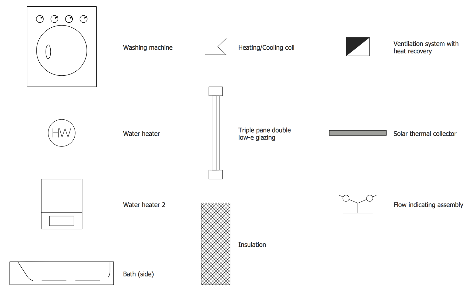
Design Elements — HVAC Schematic
HVAC Plans Examples
There are a few samples that you see on this page which were created in the ConceptDraw DIAGRAM application by using the HVAC Plans solution. Some of the solution's capabilities as well as the professional results which you can achieve are all demonstrated here on this page.
All source documents are vector graphic documents which are always available for modifying, reviewing and/or converting to many different formats, such as MS PowerPoint, PDF file, MS Visio, and many other graphic ones from the ConceptDraw Solution Park or ConceptDraw STORE. The HVAC Plans solution is available to all ConceptDraw DIAGRAM users to get installed and used while working in the ConceptDraw DIAGRAM diagramming and drawing software.
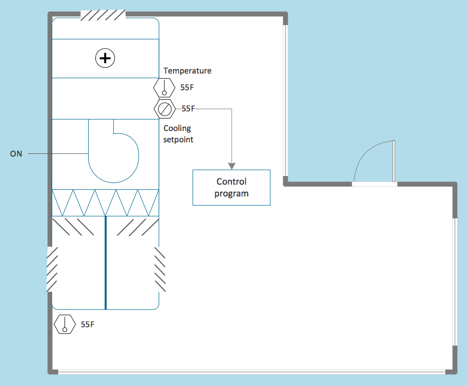
Example 1: HVAC Plan — Digital Unit Ventilator Control
This diagram was created in ConceptDraw DIAGRAM using the combination of libraries from the HVAC Plans Solution. An experienced user spent 10 minutes creating this sample.
This sample diagram created with the help of tools of ConceptDraw's HVAC Plans Solution shows a sample of HVAC-system design with all its elements labeled. The HVAC (heating, ventilation, and air conditioning) is a technology of indoor and vehicular environmental comfort. There are represented the Digital Unit Ventilator Control and the temperature sensors of air handler digital thermostat control. The thermostat (from Greek "thermos" that meanings "hot" and "statos" that meanings "are standing") is a device used to maintain the temperature near a desired setpoint by means of using the heating and cooling devices, by switching them on or off, and regulating the flow of heat transfer. The cooling setpoint is set on 55F on this HVAC diagram and is controlled by the program. The thermostats are incredibly useful and widespread today and can be met as individual devices and control units, and as the components of a heater and air conditioners.
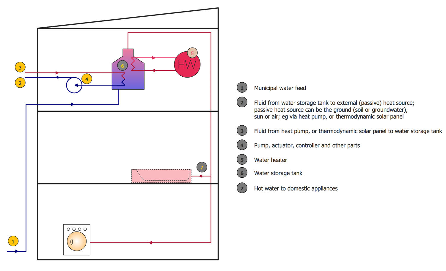
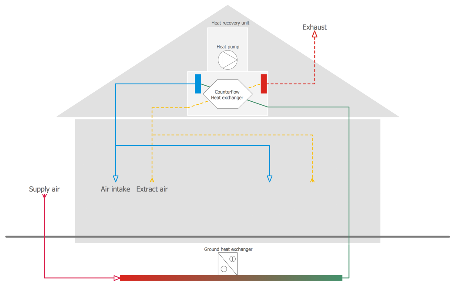
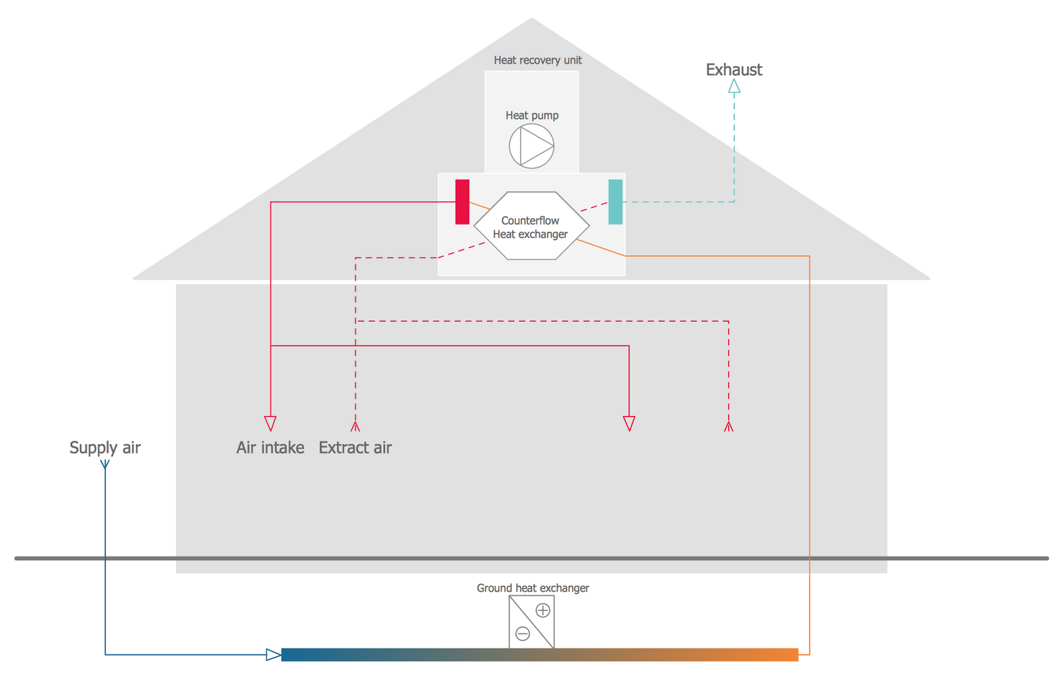
Example 2: Ventilation Unit with Heat Pump & Ground Heat Exchanger
This diagram was created in ConceptDraw DIAGRAM using the combination of libraries from the HVAC Plans Solution. An experienced user spent 15 minutes creating this sample.
This sample demonstrates a detailed plan of a Ventilation Unit with a Heat Pump and Ground Heat Exchanger, its placement within a house, schematic of internal arrangement and mechanism of work. This sample is based on the similarly named file from the Wikimedia Commons, but now it is constructed through the use of ConceptDraw’s HVAC Plans Solution. The heat recovery ventilation is an energy recovery ventilation system, which provides fresh air and improved climate control, and consists of several components depicted on this diagram, such as the Heat recovery unit, Heat pump, Counter-flow Heat exchanger and Ground heat exchanger. The air intake and extract air, supply air and exhaust are also designated on the diagram. Take into account that the use of colors and lines of varied styles can help differ and highlight various details in your plan, including the HVAC plan. The use of images, symbols and clipart is also helpful.
Example 3: Central Air Pool Heater
This diagram was created in ConceptDraw DIAGRAM using the combination of libraries from the HVAC Plans Solution. An experienced user spent 15 minutes creating this sample.
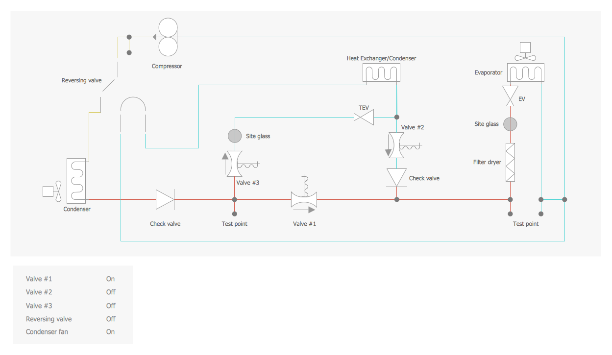
This HVAC schematics sample visualizes a diagram of a Central Air Pool Heater. It was designed on the base of illustration that accompanies the "Central Air Pool Heater" post placed at the Nathan Stratton's blog and depicts the house cool mode of a central air pool heater. Looking at this picture you can observe the movement of hot gas leaving the compressor and running to the condenser, where it condenses into a liquid. When passing through the filter dryer and the site glass to the evaporator, the liquid flashes into a gas. As for the cold gas, it runs down and outside to the compressor, and then the cycle starts once again. The HVAC Plans Solution from the Building Plans area of ConceptDraw Solution Park provides the useful drawing tools for quick, simple and effective designs for the HVAC business plan, HVAC floor plan, HVAC marketing plan of any complexity.
Example 4: Blow Through Unit Ventilator
This diagram was created in ConceptDraw DIAGRAM using the combination of libraries from the HVAC Plans Solution. An experienced user spent 5 minutes creating this sample.
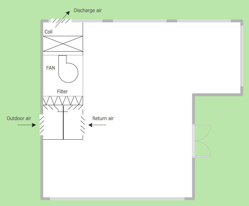
This mechanical room HVAC plan representing a Blow Through Unit Ventilator depicts the layout of air handler or air handling unit (AHU) equipment that includes the mixing chamber, fan, air filter, heat exchanger coil, diffusers. The ventilation allows ensuring the high quality of indoor air, conducting the process of replacing or changing the air within some space, also allowing controlling the air temperature and wetness, eliminating the excessive moisture if it is needed, the odors of different nature, smoke, dust, contaminants and bacteria. The ventilation lets one avoid the air stagnation in a closed space and supposes the realization of air circulating, letting the air in the outside be filled with oxygen. Extensive libraries of predesigned vector objects from the HVAC Plans Solution offered by ConceptDraw Solution Park cut the planning time for designers, architects, builders and other stakeholders allowing them to create different blueprints and plans for HVAC in a few minutes.
Example 5: Air Handler Platforms HVAC
This diagram was created in ConceptDraw DIAGRAM using the combination of libraries from the HVAC Plans Solution. An experienced user spent 10 minutes creating this sample.
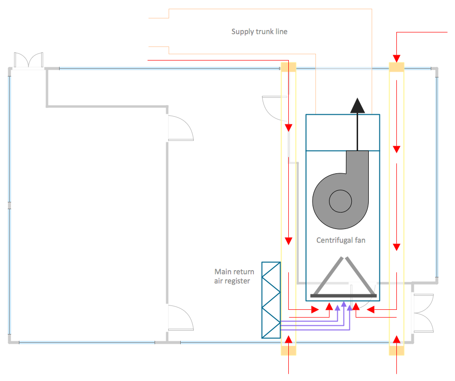
This HVAC business plan sample illustrates the air handler layout on the floor plan. The air handler or air handling unit (AHU) is a special device of supply or exhaust ventilation, which processes the air from a closed room and delivers it back to the room. The air handler is a part of the HVAC (heating, ventilating, and air-conditioning) system. Typically, it is a large metal box that contains a blower, the elements of heating and cooling, sound attenuators, dampers, filter racks and chambers. Depending on the situation, there can be used the ductwork ventilation systems. In the case of their presence, being connected to the air handlers, the ductwork ventilation systems receive the conditioned air and distribute it through the building returning then backward to AHU. HVAC plans are simply necessary for creating the complete project issue. And the use of bright colors for the arrows guarantees you that your plan will be visual, attractive, and successful.
Example 6: Apartment HVAC Plan
This diagram was created in ConceptDraw DIAGRAM using the combination of libraries from the HVAC Plans Solution. An experienced user spent 5 minutes creating this sample.
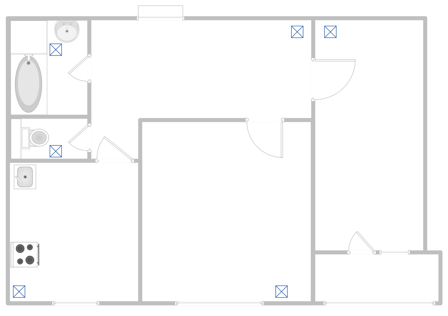
This sample demonstrates the apartment floor plan and Heating, Ventilating and Air Conditioning (HVAC) plan on it. One of the most important moments for each premise is its ventilation because it ensures the air circulation, allows maintaining the proper quality of the air, comfortable temperature and level of wetness within a closed space. It can be a mechanical ventilation or a natural ventilation, or their combination. The ventilation system within a given premise can be classified as mechanical ventilation, it is realized through the use of duct outlet diffusers, which are a special part of ventilation system intended for input and output of the air to and from the closed space, as well as for its effective mixing. The layout of exhaust ventilation duct outlet diffusers is visually represented on this diagram designed using the drawing tools of the ConceptDraw DIAGRAM software and the predesigned objects from the libraries of HVAC Plans Solution.
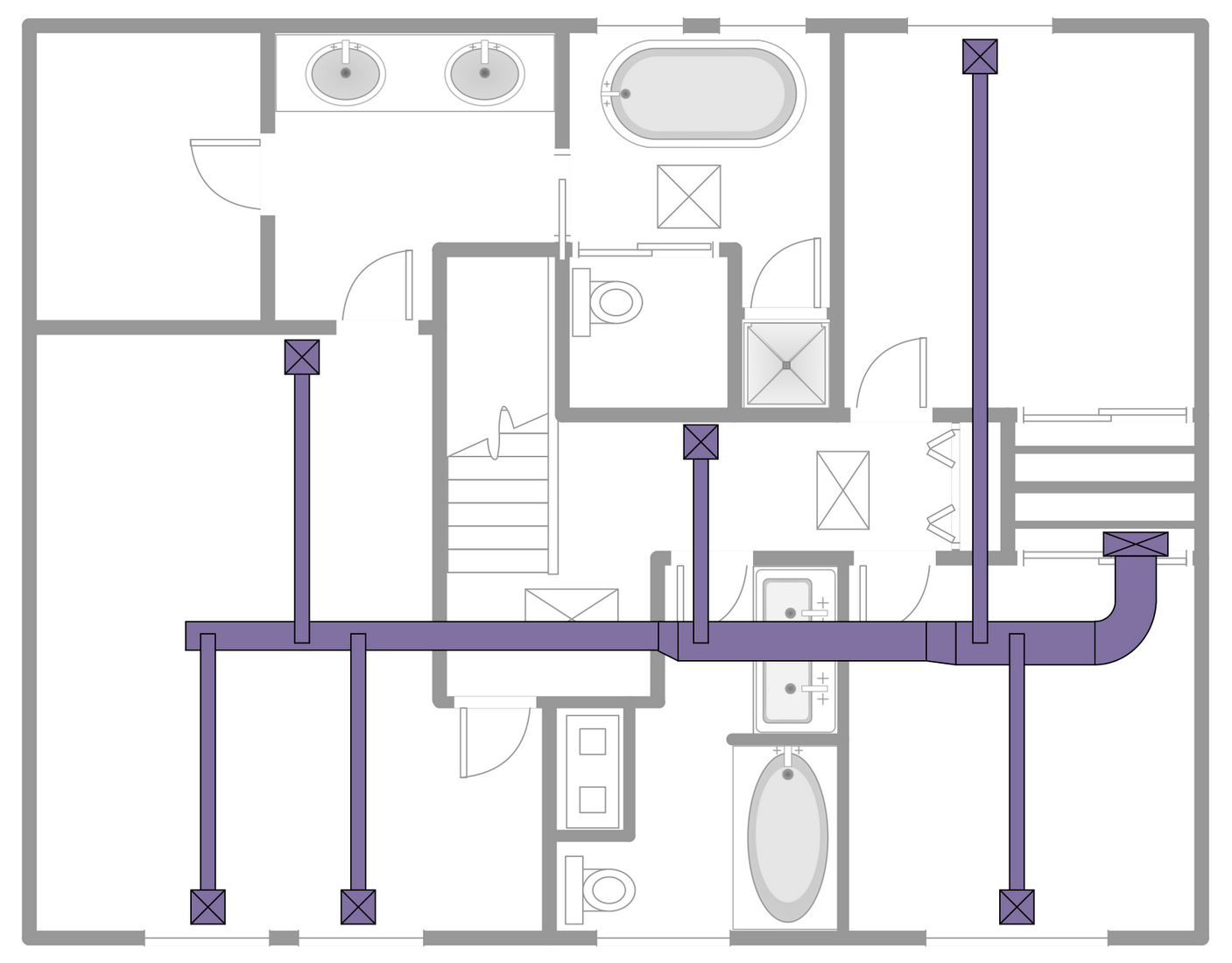
Example 7: Ductwork Layout
This diagram was created in ConceptDraw DIAGRAM using the combination of libraries from the HVAC Plans Solution. An experienced user spent 10 minutes creating this sample.
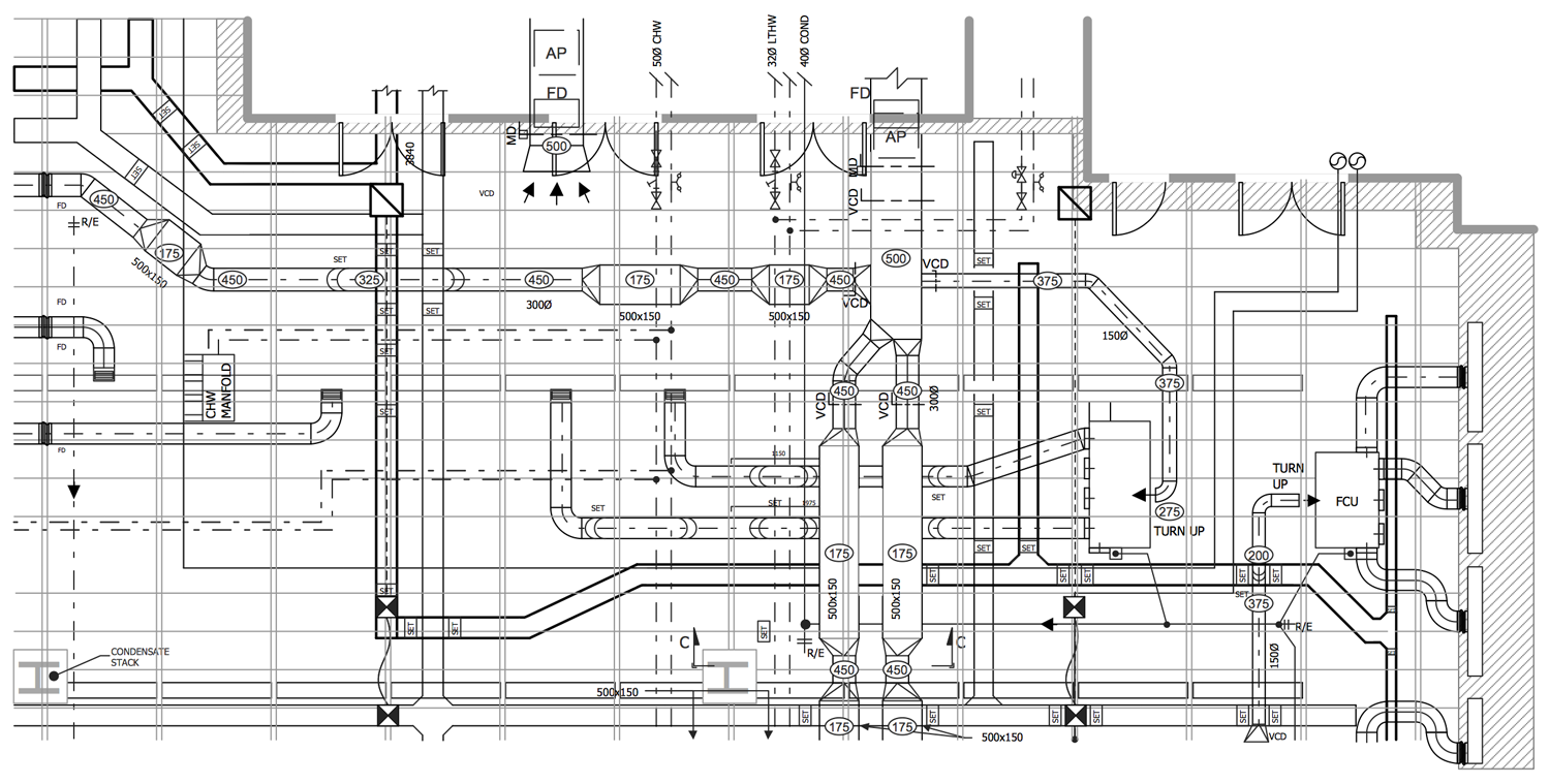
This HVAC floor plan sample illustrates the ventilation duct system layout. The ducts are ones of the basic elements in a heating, ventilation, and air conditioning system, which are used to deliver and remove the air. The ducts allow delivering the air of an acceptable quality to the room, apartment, industrial premises or any other closed space, can ensure the supply of ventilated air, and the air of required temperature or wetness mode. The planning and constructing the plan of a duct system is an important stage in building premises of different assignment. The duct design assumes the optimization, sizing, detailing, prediction and elimination of the possible pressure losses still at the stage of planning. Design easily your floor plans in the ConceptDraw DIAGRAM application using solutions from the Building Plans area and then mark on them the schemes of the ducts using the tools of the ConceptDraw's HVAC Plans Solution.
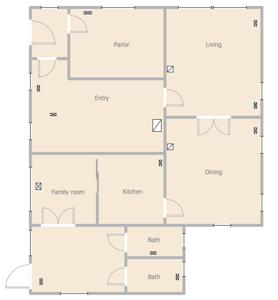
Example 8: House Ventilation
This diagram was created in ConceptDraw DIAGRAM using the combination of libraries from the HVAC Plans Solution. An experienced user spent 5 minutes creating this sample.
This house HVAC floor plan sample demonstrates the ventilation system air supply diffusers and air exhaust grilles layout. All they are placed on the detailed floor plan of an apartment, which includes a lot of rooms and auxiliary premises — entry, parlor, living room, dining room, family room, kitchen and two bath rooms. The represented system of ventilation has a mixed character. The installed devices allow realizing a mechanical ventilation, also, through the use of such planned openings as windows and doors there is realized the natural ventilation ensuring the flow of outside air to the premises. In order to not distract the attention, this plan does not contain any elements of furniture and decor that are present in a real apartment, but if necessary, you can always add them to your plan from the ConceptDraw Solution Park libraries in a matter of seconds, making the plan even more detailed.
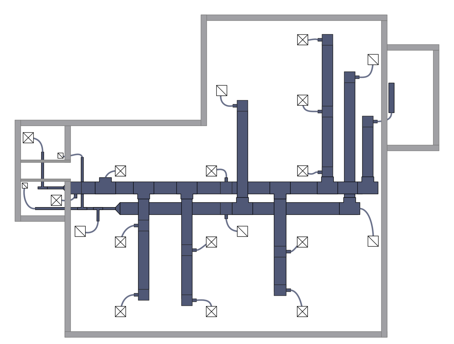
Example 9: Ventilation Duct System
This diagram was created in ConceptDraw DIAGRAM using the combination of libraries from the HVAC Plans Solution. An experienced user spent 10 minutes creating this sample.
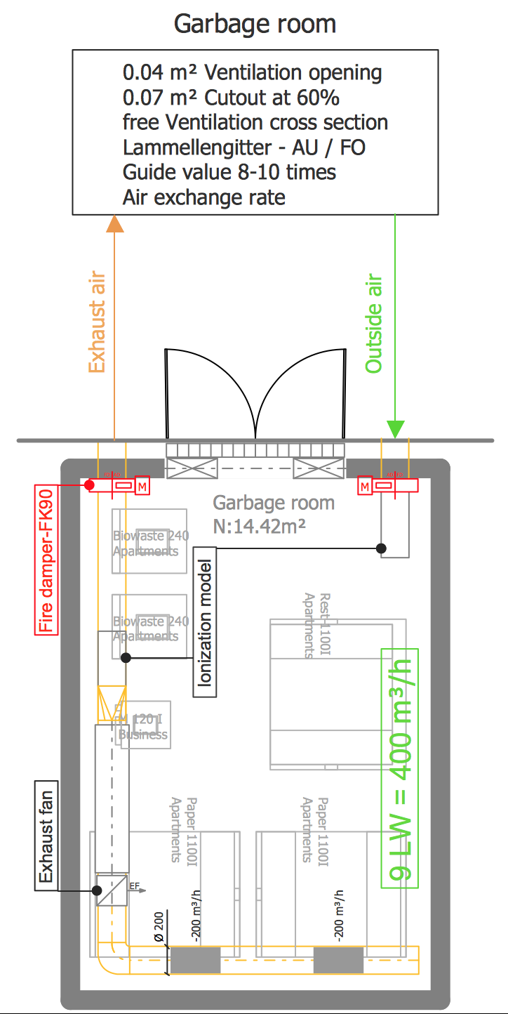
This heating, ventilation, and air conditioning (HVAC) floor plan sample depicts the ventilation duct system plan. The ventilation is an integral component, without which the normal functioning of premises is impossible. Without a correctly organized ventilation system the room can quickly become uncomfortable to be in, while the simple ventilation by opening windows in some cases cannot save the situation and is not always convenient. The properly organized ventilation allows maintaining comfortable conditions for staying, regardless of the weather outside, does not allow the moisture to appear, prevents from the bacteria and mold reproduction, and eliminates many other problems. The main components of air ventilation within the premises are the vents channels. Before you start the installation of a ventilation system, select obligatory the most suitable ventilation’s type and construct the detailed plan taking into account all specifics of the room and in correspondence with a selected type of ventilation and safety standards.
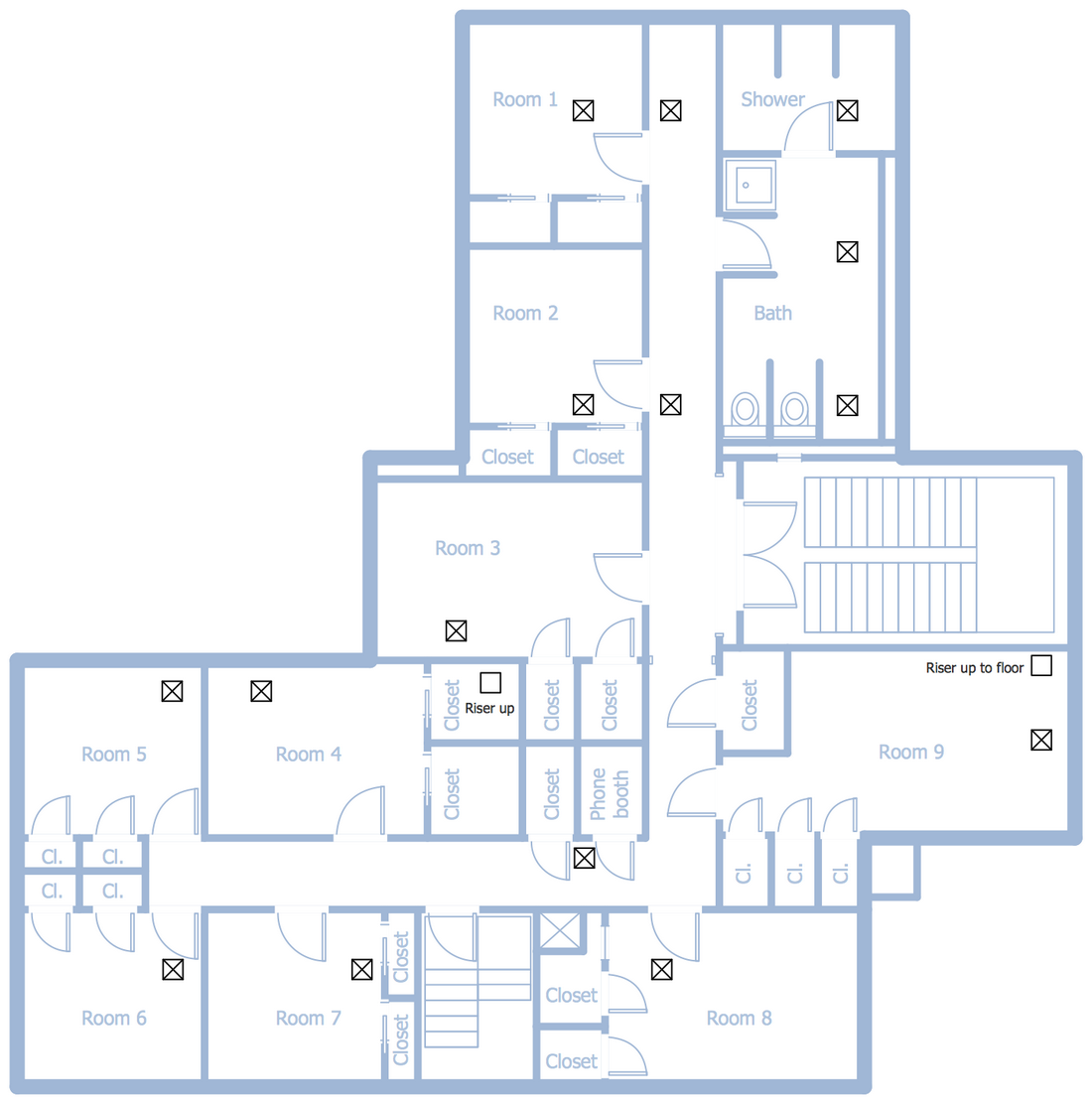
Example 10: School HVAC Plan
This diagram was created in ConceptDraw DIAGRAM using the combination of libraries from the HVAC Plans Solution. An experienced user spent 5 minutes creating this sample.
This HVAC sample depicts the realization of heating, ventilation, and air conditioning in school shows on the school plan the layout of air conditioning ductwork inlets and outlets. Most often when talking about the air conditioning, we mean the air cooling or heating, but in fact, the air conditioning has a much larger range of properties and capabilities. The air conditioning allows changing the properties of air within the premises so that it will be comfortable, of a proper quality, an appropriate temperature and humidity, free from the external odors, cleaned off the smallest alien fractions. The air conditioning and air purification are necessary for any room, but special attention in terms of an air quality and improvement the thermal comfort is paid to such public places as schools, kindergartens, universities, hospitals, clinics. It is in view of the importance of HVAC system, in ConceptDraw DIAGRAM application was created this HVAC plan sample for school premises.
Inside
What I Need to Get Started
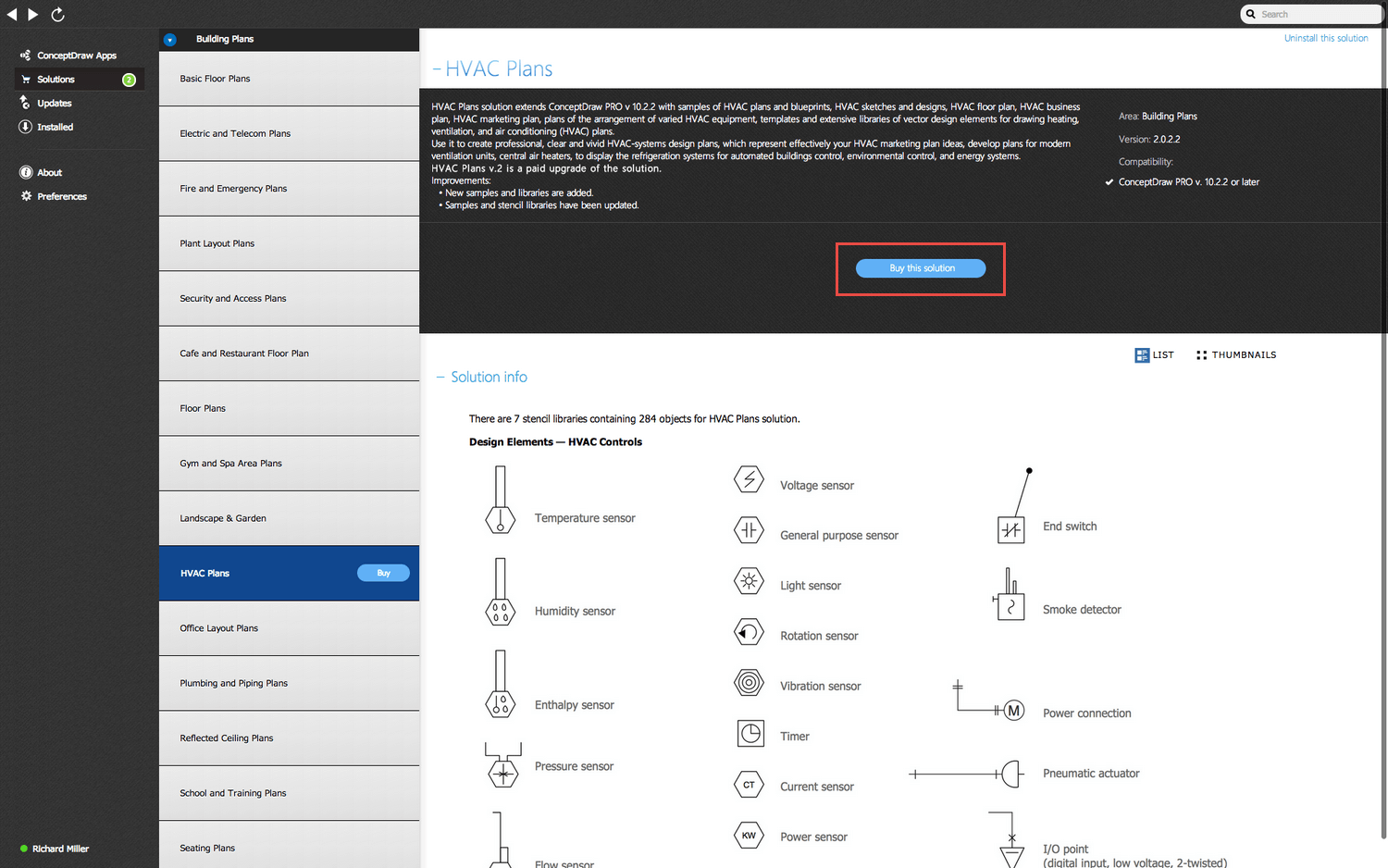
After ConceptDraw DIAGRAM is installed, the HVAC Plans solution can be purchased either from the Building Plans area of ConceptDraw STORE itself or from our online store. Thus, you will be able to use the HVAC Plans solution straight after.
How to install
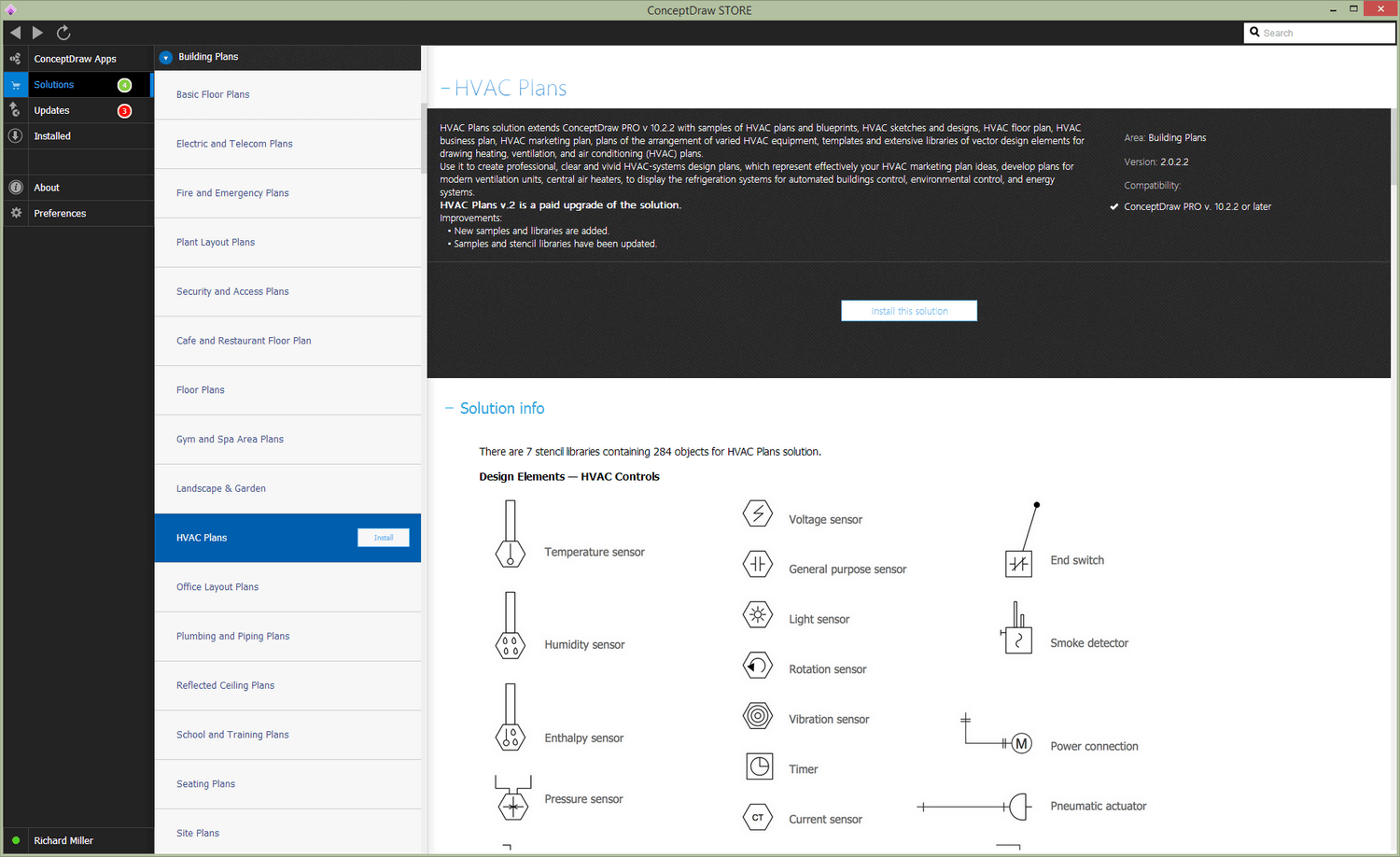
First of all, make sure that both ConceptDraw STORE and ConceptDraw DIAGRAM applications are downloaded and installed on your computer. Next, install the HVAC Plans solution from the ConceptDraw STORE to use it in the ConceptDraw DIAGRAM application.
Start using
Start using the HVAC Plans solution to make the professionally looking floor plans by adding the design elements taken from the stencil libraries and editing the pre-made examples that can be found there.
