UML Business Process
What is UML in Business?
Working on the business process modelling means being involved in the systems engineering, known to be the activity of representing different processes of some particular enterprise, when the current process is improved or analysed. business process modelling is such kind of business activity, which is known to be performed by the business analysts.
The mentioned business analysts are those who are in charge for providing an expertise in any given modelling discipline. The subject matter experts may be also involved in the mentioned business activity, being specialized having the knowledge of the processes which are being modelled. Although, more commonly a team of both mentioned categories of the specialists is involved in the described process of the business modelling.
The process model, optionally, can be derived directly from events' logs by using the so-called “process mining tools”. Some of the business objectives are known to be the reducing of the cycle time or increasing of the process speed. In order to increase the quality as well as to reduce costs, such as materials, labour, scrap, capital costs, etc., the modelling is widely used. Any manager’s decision to invest in some particular business process modelling can be often motivated by the need of documenting the given requirements for some particular IT project.
The so-called “change management programs” are known to be often involved in the process of putting any of the improved business processes into practice. Thus, the vision of the mentioned models within the business process modelling activity becomes nowadays more and more executable.
Any business model is simply a framework used for creating social, economic, and other forms of value. Such term can be also used for any informal as well as formal descriptions used for representing the core aspects of any particular business. The “core aspects” may be purpose, strategies, infrastructure, offerings, organizational structures, trading practices, as well as operational policies and processes.
Any business model can be also characterized as a method of doing business used by a company to sustain itself, making sure it makes enough money, specifying where exactly it is positioned among its competitors in the value chain.
What are the Types of Business Processes?
Any business process is known to be a collection of structured as well as related tasks or activities, producing a specific product or service for a customer or for many different customers. The main types of business processes are the management processes, supporting processes and operational processes. Management processes are known to be governing the operations within some given system. The term of the “management processes” include the strategic management and the corporate governance. Operational processes are those, constituting the core business as well as creating the primary value stream. The examples of such processes may be the process of the manufacturing, purchasing, sales and marketing. The supporting processes are used for supporting the core processes: accounting, technical support, recruitment, etc.
Any business process can be split into a few different sub-processes, having their own attributes, but at the same time contributing to achieving the goal of the so-called “super-process”. While conducting the analysis of the business processes, it is important to take into consideration the need for the mapping of such processes as well as the sub-processes all the way down to reach the very core activity level.
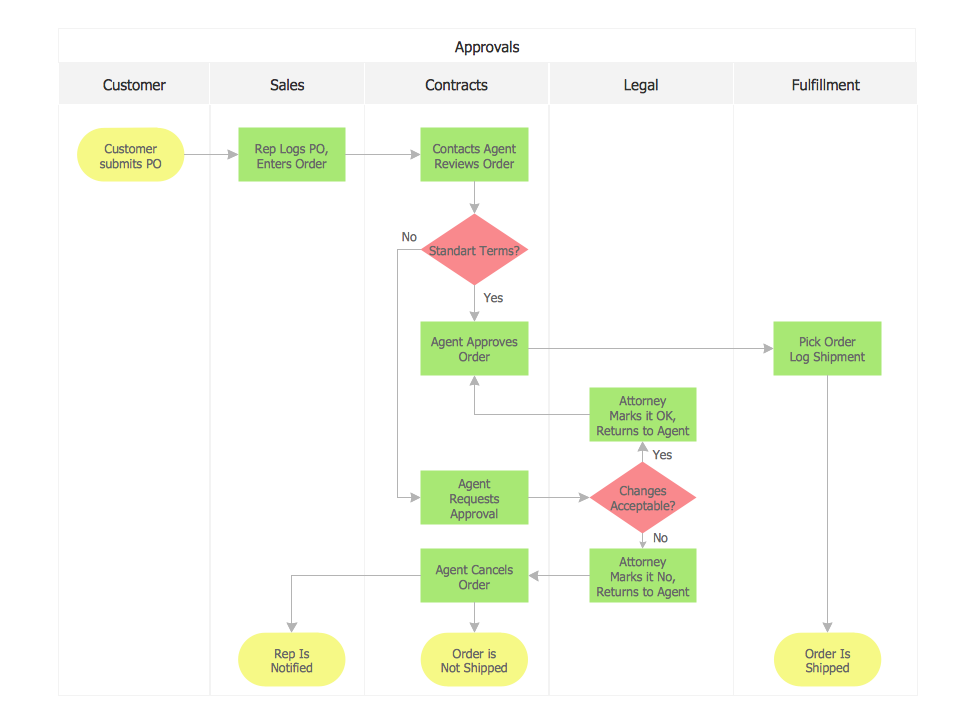
A business process model itself is a model of one or more than one business processes, defining the ways the operations can be carried out for accomplishing the intended goals within a particular organization. Such models remain an abstraction, depending on the intended use of the mentioned model, describing the integration or the workflow between different business processes, usually being constructed on the multiple levels.
A workflow is simply a depiction of a sequence of the operations. It is known to be declared as a simple or complex mechanism, work of a person, of an organization of staff, of machines or of a group of different persons. It is usually seen as any abstraction of real work, segregated into work split, workshare or some other types of ordering, being a view of a real work under some chosen aspect for the control purposes.
The commonly and widely used business process modelling tools are those providing their business users with the ability of modelling their business processes, implementing as well as executing the described models, and refining those models which are based on the so-called “as-executed data”. Shortly, they simply provide the transparency into the business processes and the centralization of the execution metrics and the corporate business process models.
There are a few types of the so-called business process models, such as the so-called “business reference models”, which are known to be simply the reference models, which are concentrating on the organizational and the functional aspects of an enterprise, a government agency or a service organization. Any reference model represents something that embodies the basic idea or goal of something, used for describing the business operations of an organization, being be constructed in layers, offering a foundation for the analysis of the technology, data, performance and different service components.
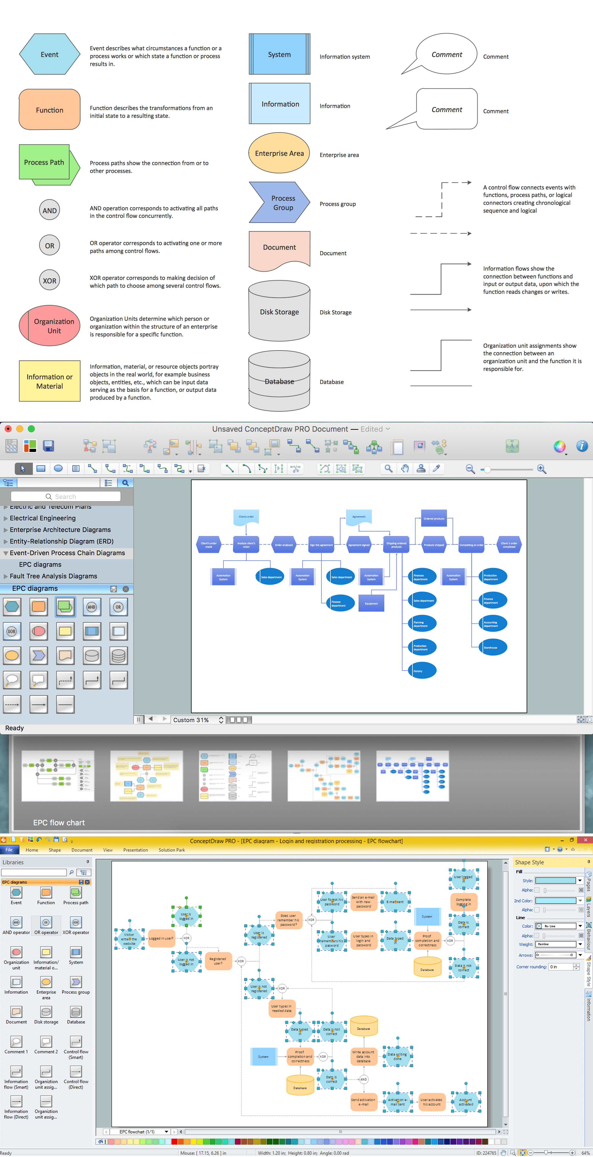
Apart from the mentioned above, there are also other types of business reference models, depicting the relationship between the business functions, business processes, as well as the business area's business reference models. Another type can be a so -alled UML business model, used within the UML business processes. Any of the mentioned above as well as those which were not described in this article, but still commonly used models, can be always created with help of ConceptDraw DIAGRAM — one of the best existing diagramming and drawing applications.
Any of the needed UML diagrams can be always made with help of the Rapid UML solution from ConceptDraw STORE used while working in the ConceptDraw DIAGRAM software.
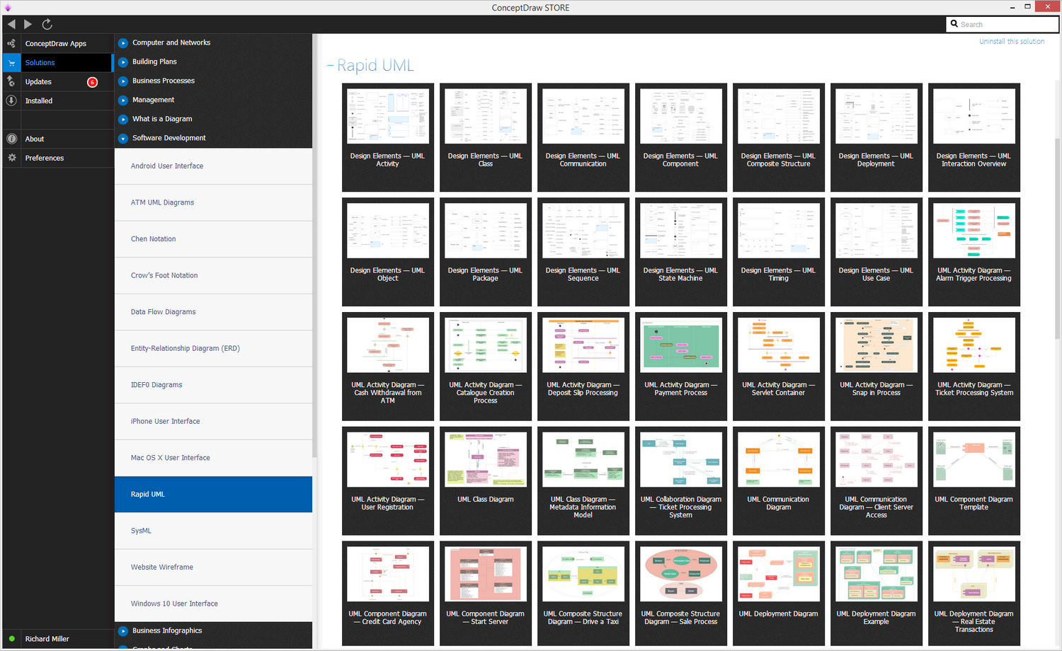
The Rapid UML solution provides diagram examples, templates and vector stencils libraries for quick and easy drawing all types of UML 2.x and 1.x diagrams:
- UML Activity Diagrams
- UML Communication (collaboration) Diagrams
- UML Component Diagrams
- UML Composite Structure Diagrams
- UML Deployment Diagrams
- UML Interaction Overview Diagrams
- UML Object Diagrams
- UML Package Diagrams
- UML Sequence Diagrams
- UML State Machine Diagrams
- UML Timing Diagrams
- UML Use Case Diagrams
The Rapid UML solution uses ConceptDraw RapidDraw techniques of quick diagram creation in the ConceptDraw DIAGRAM software.
The Rapid UML solution is a part of the Software Development area of ConceptDraw STORE.
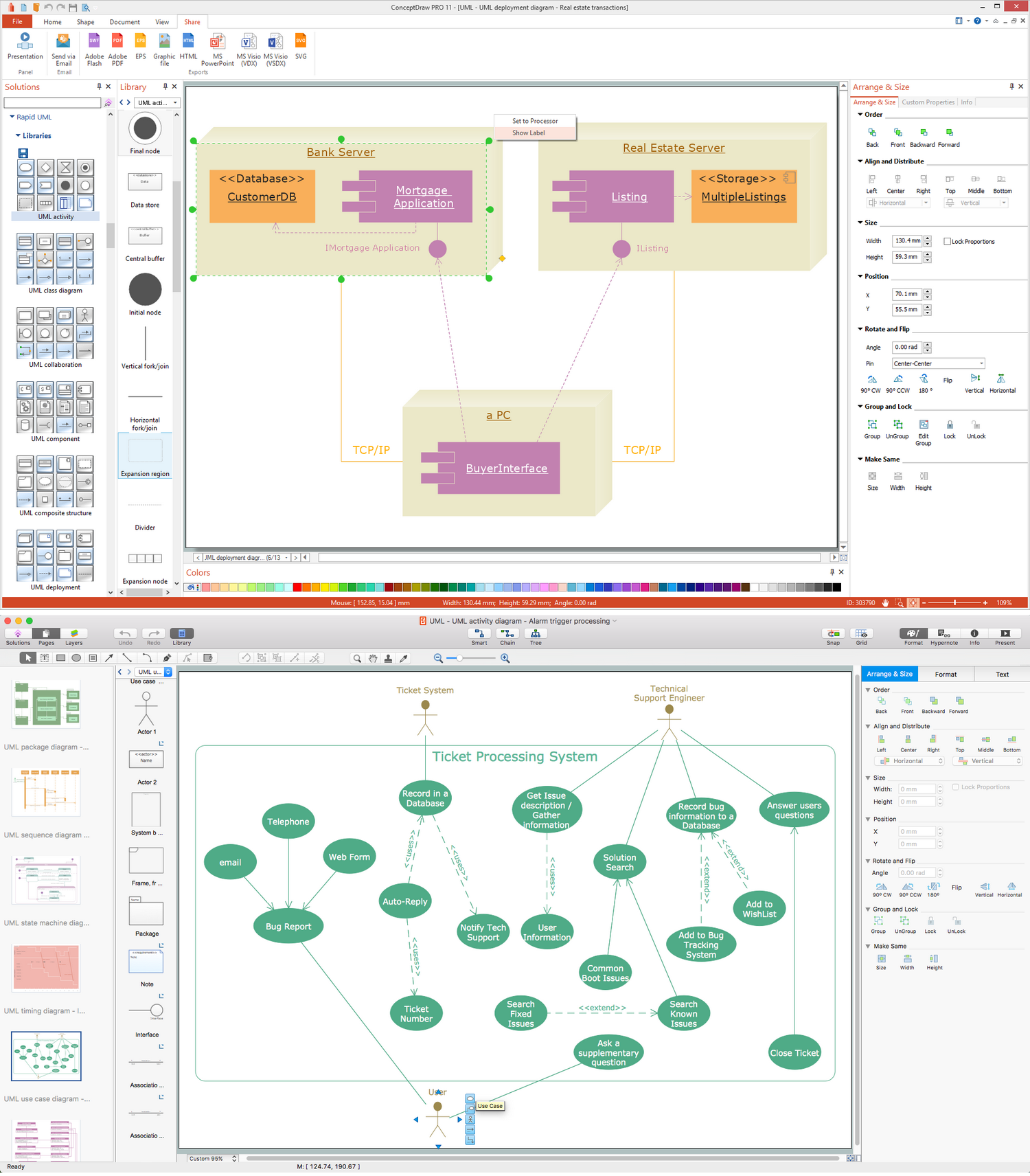
”A use case diagram at its simplest is a representation of a user's interaction with the system and depicting the specifications of a use case. A use case diagram can portray the different types of users of a system and the various ways that they interact with the system. This type of diagram is typically used in conjunction with the textual use case and will often be accompanied by other types of diagrams as well.” [Use Case Diagram. Wikipedia]

Example 1. UML 1.x Activity diagram for a guided brainstorming process.
”Activity diagrams are graphical representations of workflows of stepwise activities and actions with support for choice, iteration and concurrency. In the Unified Modeling Language, activity diagrams are intended to model both computational and organisational processes (i.e. workflows). Activity diagrams show the overall flow of control.” [Activity diagram. Wikipedia]
ConceptDraw DIAGRAM is a Perfect Tool for:
- Designing and planning tasks such as:
- Jacobson Use Cases Diagram
- SSADMN Diagram
- Yourdon and Coad Diagram
- Command OLE Diagram
- Block Diagrams
- Data Modeling Diagram
- SysML Diagram
- Chen RED Diagram
- Martin RED Diagram
- IDEF0 Diagram
- Booch OOD Diagram
- Gane Sarson Diagram
- Memory Object Diagram
- Data Flow Diagram
- FlowCharts
- Graphic User Interface (GUI)
- UML Diagram
- Program Structure Diagrams
- ORM Diagram
- Developing Visualization Solutions
- Project Planning (Gantt Charts, Timelines, Project Schedules)