ORM Diagram
What is an ORM Diagram?
Object-role modelling can be used for data modelling in software engineering business activity, being simply the semantics of a universe of discourse. The final object-role models, which were coined in the 1970s, use different graphical symbols, based on set theory as well as first order predicate logic, which enables the modeller to make an unambiguous definition of a so called “arbitrary universe of discourse”. Basically, object-role models are graph database models, better analysed and designed to benefit the relational database design.
ORM based tools as well as object-role models have been used for more than 30 years and still are very popular. The mentioned object-role models have been used for modelling the business rules, data warehouses, web forms, requirements engineering forms and XML-Schemas. Originally, the roots of object-role models can be traced to research into semantic modelling for information systems during the 1970s in Europe, having an early contribution came in 1973. In that year Michael Senko wrote about data structuring in the “IBM Systems Journal” and in 1974 Jean-Raymond Abrial contributed an article about Data Semantics, followed by Eckhard Falkenberg, who published the papers in June 1975 mentioning the object-role models, as well as in 1976 again.
Already in 1989 the thesis on object-role model was completed by Terry Halpin, incorporating several extensions and, of course, providing the first full formalization of the approach. Same year, he and G.M. Nijssen wrote a book named "Conceptual Schema and Relational Database Design", as well as several joint papers. In those papers they provided the first formalization of the object-role modelling, writing six more books and over 160 technical papers about it later.
The object-role modelling can be also used in combination with standardised relation types, involving the associated roles as well as a taxonomy (the practice and science of classification) of concepts and machine-readable dictionary. Standardisation of the so called “relation types” (also known as “fact types”), concepts and roles enables increased possibilities for model reuse as well as for model integration. All object-role models are based on elementary facts. The mentioned facts can be expressed in many different types of diagrams, based on the object-role modelling process, which can be verbalised into natural language.
With object-role modelling, the propositions (which can be related to the objects of belief, primary bearers of truth-value as well as other “proportional attitude”, the meanings of declarative sentences and the referents of that-clauses) are abstracted into "fact types", when the individual propositions are regarded as “sample data”. The difference between an "elementary fact" and a "fact" itself is that an elementary fact cannot be simplified without loss of meaning. The mentioned "fact-based" approach facilitates transforming, modelling and querying information from any needed domain.
Object-role models are known to be “attribute-free”, treating all elementary facts as relationships and the decisions for grouping facts into structures, as implementation concerns irrelevant to semantics, which differs them from the models in the Unified Modelling Language and the entity-relationship methods. Object-role models improve the semantic stability, enabling any verbalization into natural language in a way of avoiding attributes in the base model.
The so called “fact-based modelling” includes procedures for mapping facts to attribute-based structures and all fact-based textual representations are based on formal subsets of native languages. Thus, the object-role models are simpler to understand by those people, who have no technical education. Although, fact-based graphical notations are known to be more expressive, to compare to the Unified Modelling Language and the entity-relationship ones. Also, it’s important to remember that object-role model can be automatically mapped to deductive and relational databases.
Object-role modelling 2 is simply the latest generation of object-role modelling, using the main objectives for the ORM 2 graphical notation, which are support for new features (such as role path delineation, modalities and closure aspects), more compact display of ORM models with no need of compromising clarity, an improved internationalization (for example, to avoid English language symbols), the simplified drawing rules for facilitating creation of a graphical editor and an extended use of views for selectively suppressing/displaying detail.
System development usually involves such stages, as feasibility study, requirements analysis, design of both operations and data as well as logical design, external design, internal design as well as its implementation, prototyping, validation, testing and, finally, maintenance. The steps of the schema design procedure include drawing the fact types and applying a population check, transforming familiar information examples into elementary facts and applying quality checks, checking for entity types that are meant to be combined, noting any arithmetic derivations, adding uniqueness constraints, checking arity of fact types, adding mandatory role constraints and checking for logical derivations, adding value, set comparison as well as subtyping constraints, adding other constraints and performing final checks.

Example 1. ORM Diagram
The mentioned conceptual schema design procedure of object-role modelling focuses on the design as well as analysis of data and it should be taken into consideration while creating the so called object-role modelling diagrams, which can be simply created in ConceptDraw DIAGRAM software within a very short period of time having all the needed tools, provided by the solutions, that all can be found in the ConceptDraw STORE — another application, developed by the CS Odessa IT specialists in order to simplify all ConceptDraw DIAGRAM users’ processes of drawing.
ConceptDraw DIAGRAM is a Perfect Tool for:
- Designing and planning tasks such as:
- Jacobson Use Cases Diagram
- SSADMN Diagram
- Yourdon and Coad Diagram
- Command OLE Diagram
- Block Diagrams
- Data Modeling Diagram
- SysML Diagram
- Chen RED Diagram
- Martin RED Diagram
- IDEF0 Diagram
- Booch OOD Diagram
- Gane Sarson Diagram
- Memory Object Diagram
- Data Flow Diagram
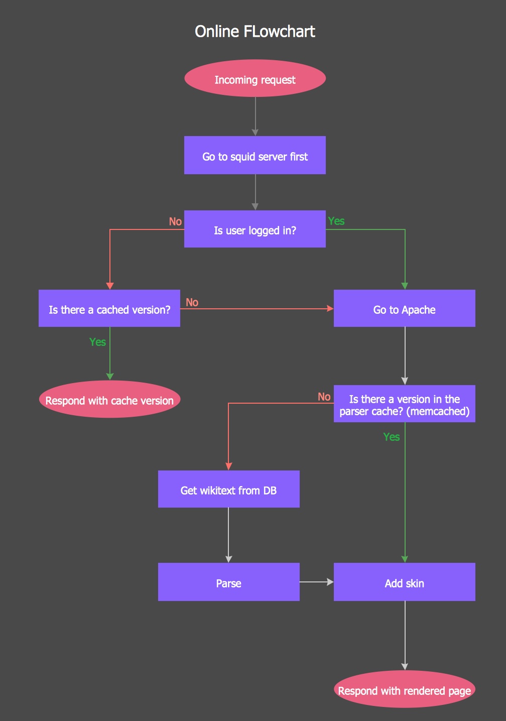
- FlowCharts
- Graphic User Interface (GUI)
- UML Diagram
- Program Structure Diagrams
- Developing Visualization Solutions
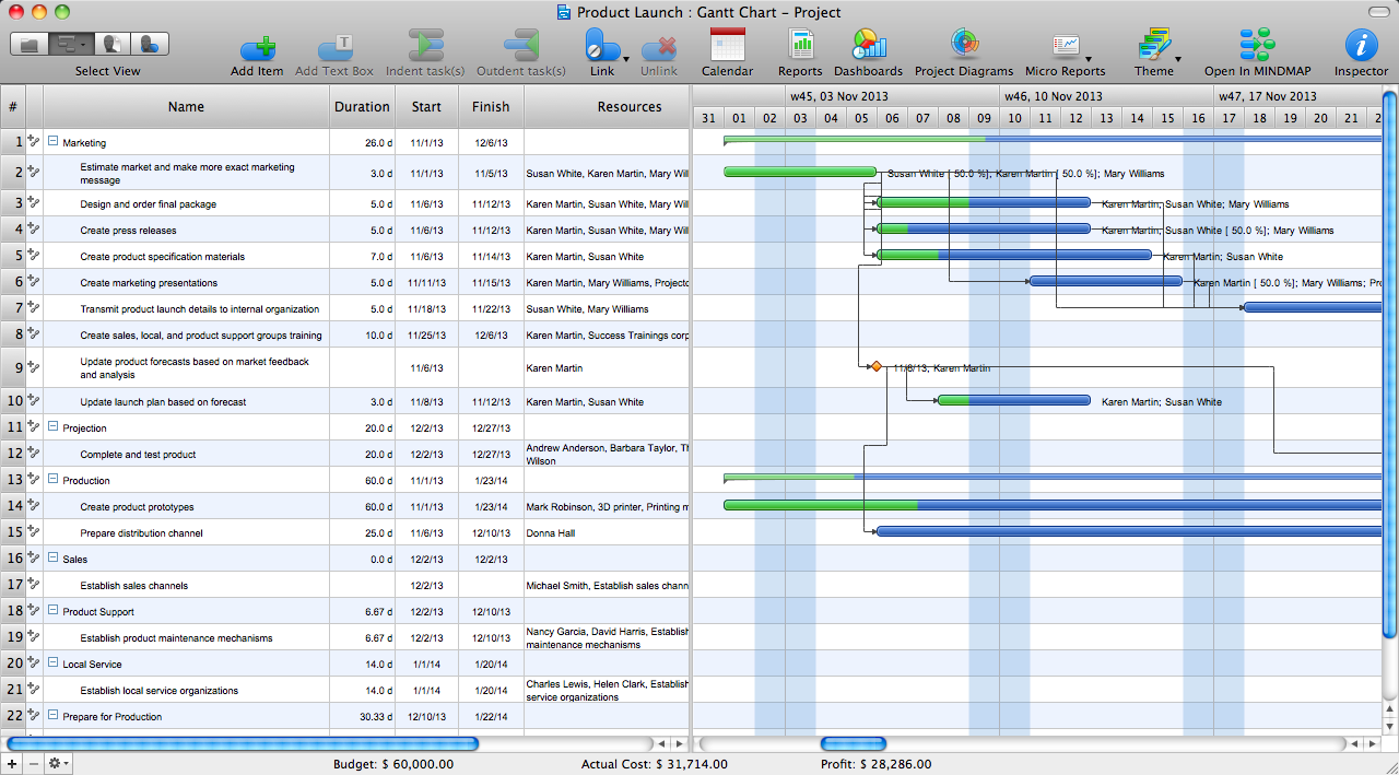
- Project Planning (Gantt Charts, Timelines, Project Schedules)