Example 1. Onion Diagram Process Design
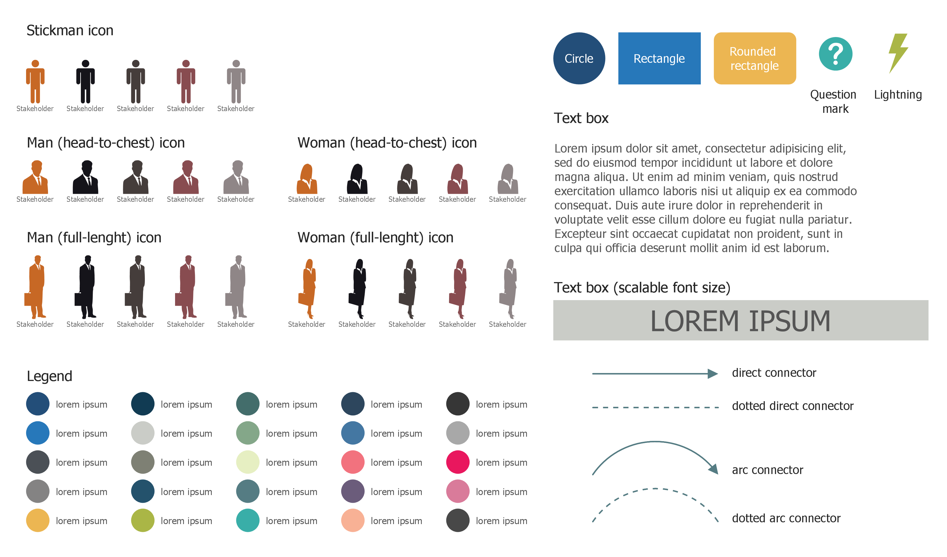
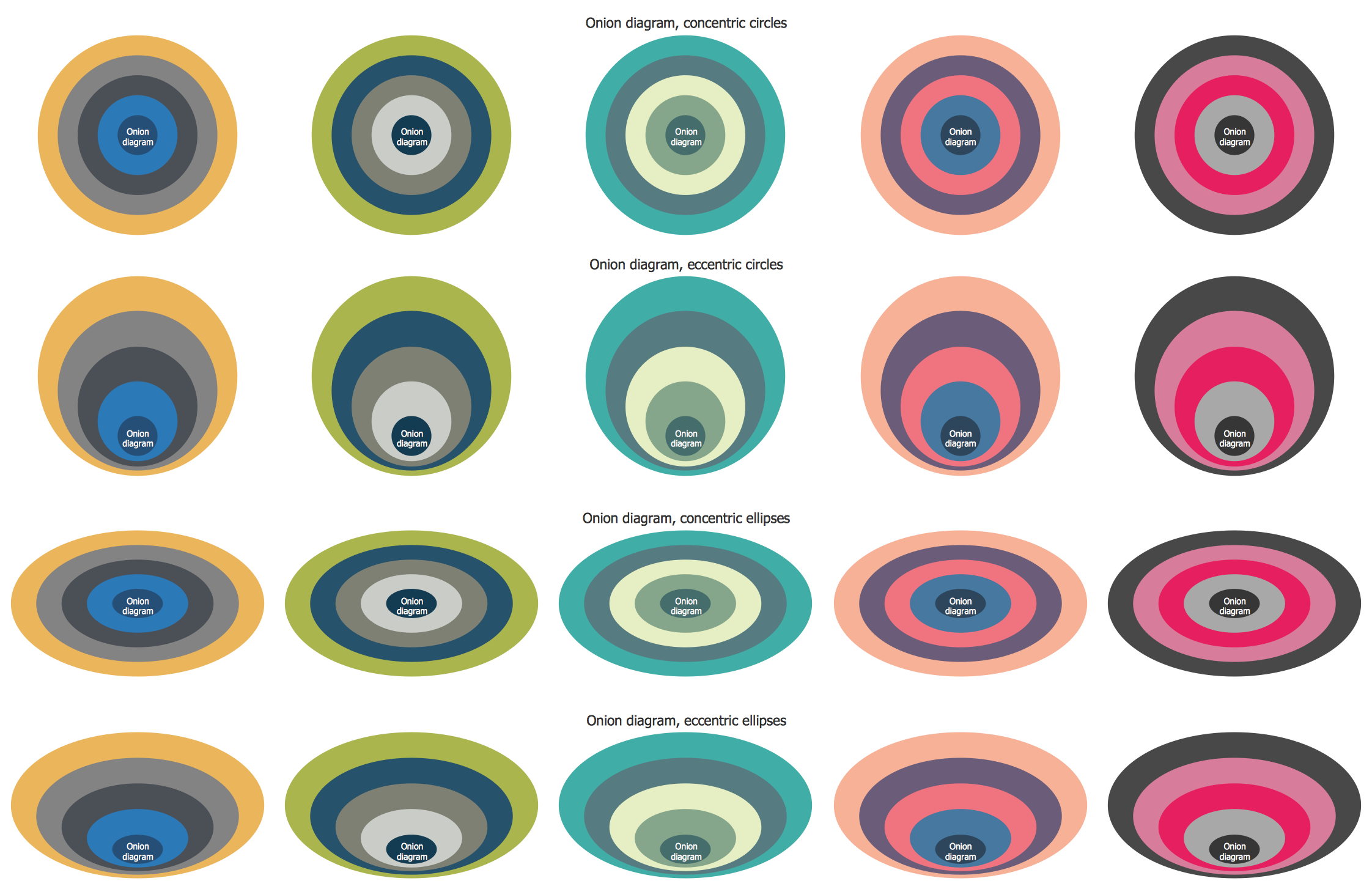
The drawing tools of the Stakeholder Onion Diagrams Solution are so much useful for effective Onion Diagram process design. First of all, it is worth to note collection of predesigned vector objects developed by professional designers for Stakeholder Onion Diagrams Solution. These are 91 objects grouped in 3 libraries.
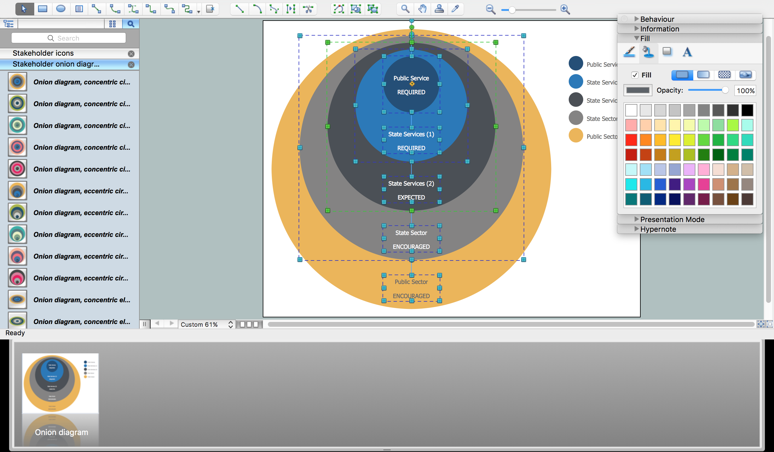
Start create your diagram and evaluate the usability of already predesigned objects! You only need to double-click the icon at the library to quickly add chosen object to the middle of your document. Then you are able to add your data and make needed changes, including the coloring and style changes, to make your diagram more beautiful and successful.
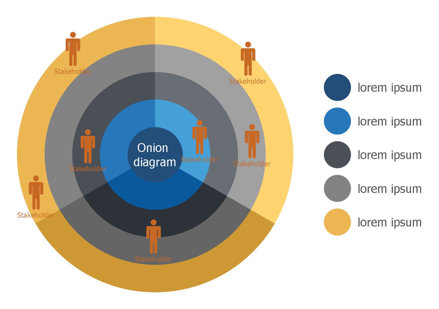
Example 2. Onion Diagram With 3 Sectors Template
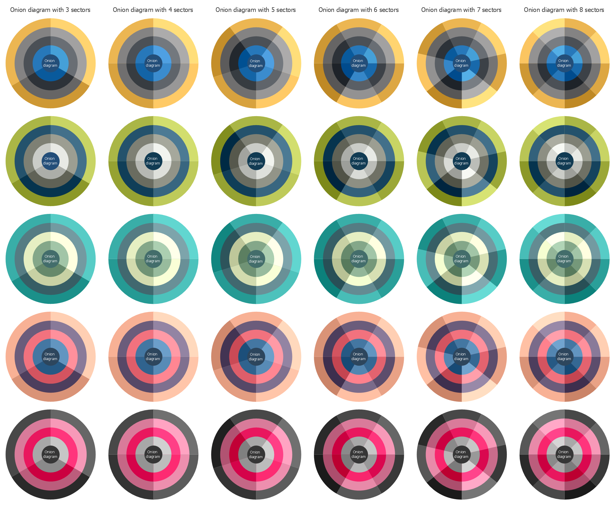
You will also benefit from the set of Stakeholder Onion Diagrams samples and templates offered by Stakeholder Onion Diagrams solution in ConceptDraw STORE. You can choose any desired from the offered that meets your requirements and change it for your needs.
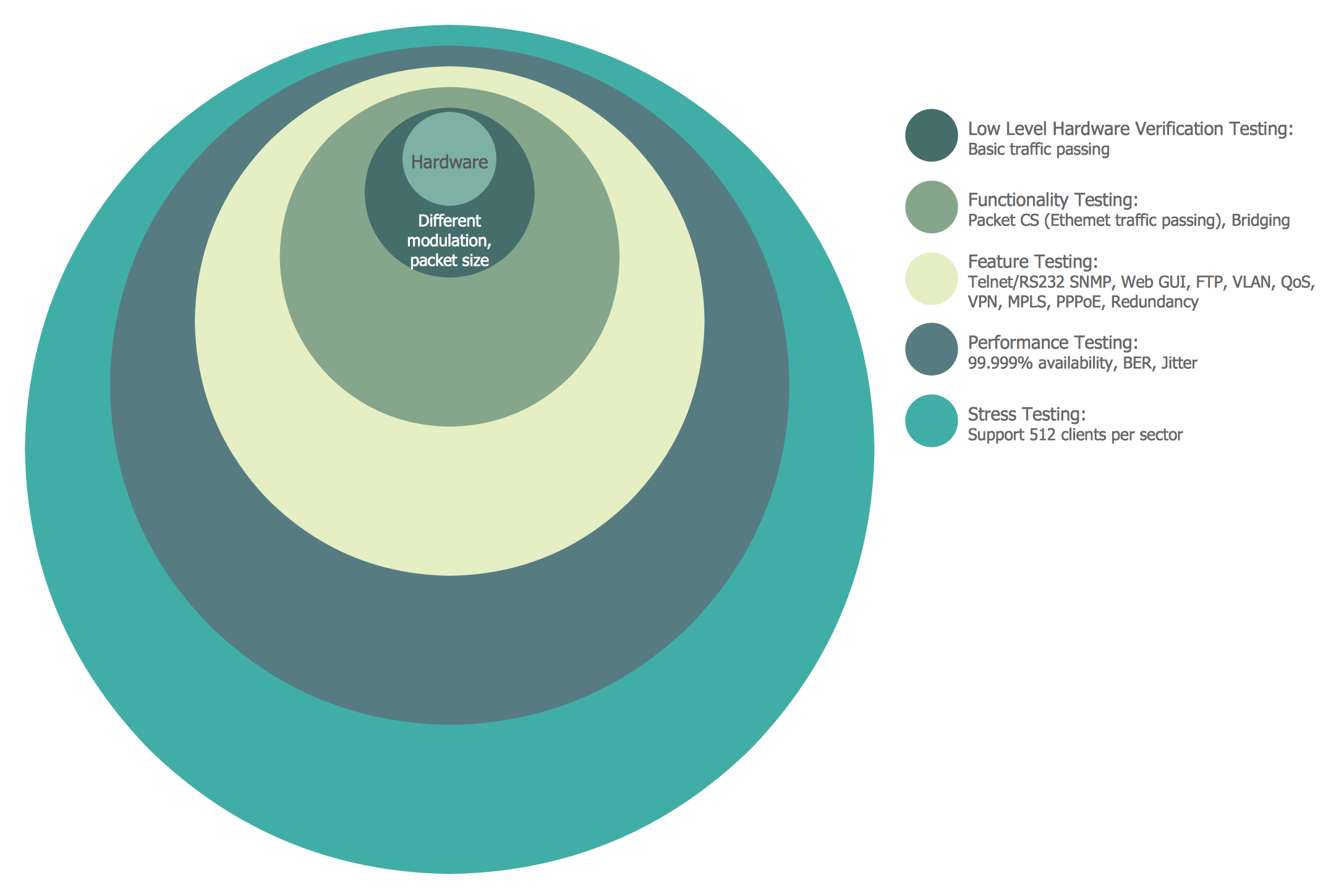
Example 3. WiMAX Development Onion Diagram
The samples and template you see on this page were created in ConceptDraw DIAGRAM software using the objects from the libraries of Stakeholder Onion Diagrams solution. An experienced user spent 10 minutes creating each of them.
Use the Stakeholder Onion Diagrams Solution for ConceptDraw DIAGRAM software for quick, easy and effective Onion Diagram process design.
All source documents are vector graphic documents. They are available for reviewing, modifying, or converting to a variety of formats (PDF file, MS PowerPoint, MS Visio, and many other graphic formats) from the ConceptDraw STORE. The Stakeholder Onion Diagrams Solution is available for all ConceptDraw DIAGRAM users.
TEN RELATED HOW TO's:
Desbloquee el lenguaje de los diagramas de flujo con nuestra guía de símbolos de diagramas de flujo. 🔸 Todo lo que necesita saber sobre los conceptos básicos del diagrama de flujo, desde ✔️ puntos de decisión hasta ✔️ pasos del proceso, explore el significado detrás de cada símbolo y domine el arte de crear representaciones visuales claras y efectivas de sus procesos.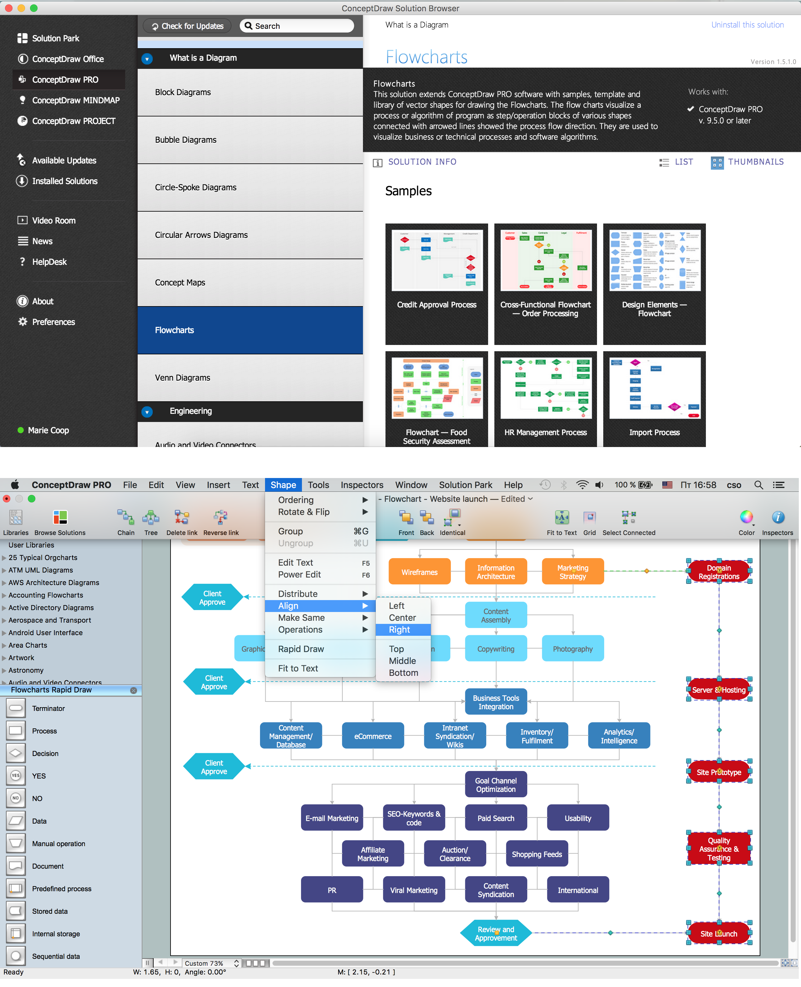
Picture: Symboles Organigramme
Related Solution:
Sales process engineering is a complex and labour-intensive process which requires a lot of time, efforts, and powerful software. We recommend to use the ConceptDraw DIAGRAM software enhanced with Sales Flowcharts solution from the Marketing area of ConceptDraw Solution Park. It gives the possibility to easy illustrate all sales process steps and their results.
Picture: Sales Process Steps
Related Solution:
The library with 40 vector stencils is included in the ConceptDraw Value Stream Mapping solution.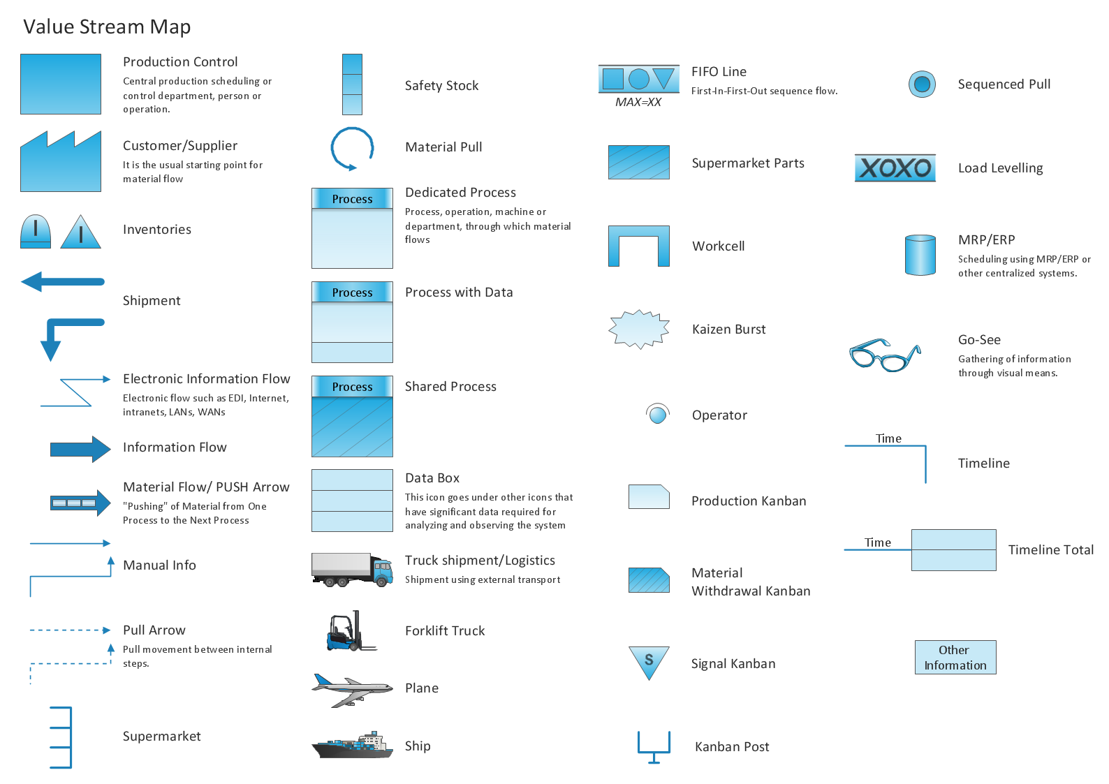
Picture: Value Stream Mapping Icons
Related Solution:
Use ConceptDraw DIAGRAM software with Flowcharts Solution to create Process Flow Charts, Flow Chart Process Maps, and High-Level Process Flow Charts to illustrate ✔️ high-level processes in industrial, chemical, and process engineering, ✔️ major plant processes, ✔️ minor details
Picture: Process Flow Chart
Related Solution:
Every engineering project starts from a terms of reference document. The next stage of developing is a technical drawing, which requires using appropriate software. However, revisions and discussions about requirements are possible at any stage of development.
This technical drawing demonstrates a schematic flow diagram of pulp reclaiming. This diagram of magnetite pulp reclaiming is created using ConceptDraw Chemical and Process engineering solution, The solution delivers more than 460 vector graphic icons and connectors. Generally, it is intended for designing process and instrumentation diagrams (P&ID) for chemical and process engineering. block flow diagrams (BFD), process flow diagrams (PFD) for chemical industry.
Picture: Technical Drawing Software
Related Solution:
ConceptDraw DIAGRAM software extended with Sport Field Plans Solution from the Building Plans Area is a perfect software for drawing professional looking playground layout of any complexity.
Picture: Playground Layout
Related Solution:
Use ConceptDraw Expanded Objects library with 14 objects from BPMN. Expanded Objects are used for rapid design of Business Process Diagrams.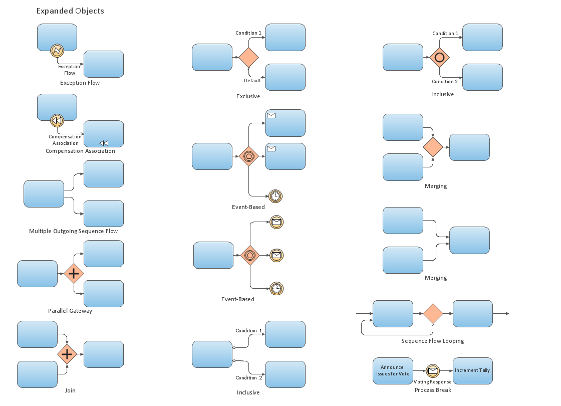
Picture: Business Process Elements: Expanded Objects
Create professional business process diagrams using ConceptDraw Gateways library with 8 objects from BPMN.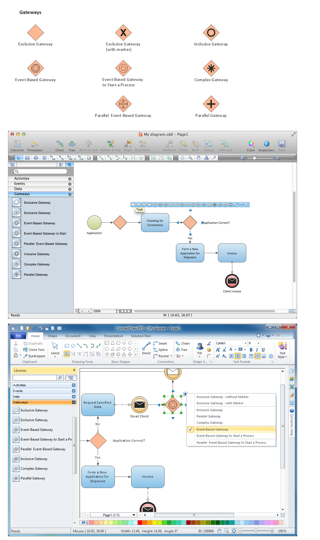
Picture: Diagramming Software for Design Business Process Diagrams
ConceptDraw DIAGRAM diagramming and vector drawing software provides the unique Flowcharts Solution from the Diagrams Area of ConceptDraw Solution Park with variety of vector objects libraries and collection of examples Flowchart. Each example flowchart included in Flowcharts solution is a real help in drawing process, it can be the good base or perfect source of inspiration.
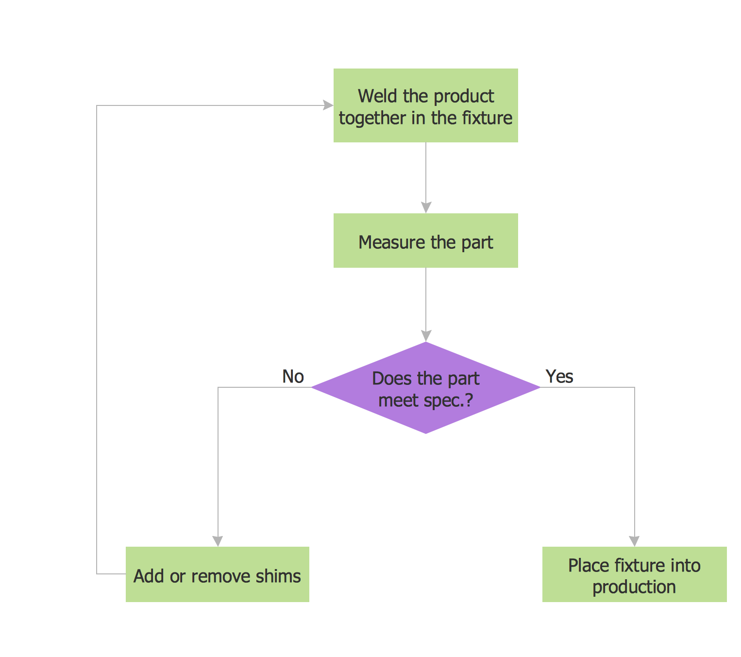
Picture: Examples Flowchart
Related Solution:
While creating flowcharts and process flow diagrams, you should use special objects to define different statements, so anyone aware of flowcharts can get your scheme right. There is a short and an extended list of basic flowchart symbols and their meaning. Basic flowchart symbols include terminator objects, rectangles for describing steps of a process, diamonds representing appearing conditions and questions and parallelograms to show incoming data.
This diagram gives a general review of the standard symbols that are used when creating flowcharts and process flow diagrams. The practice of using a set of standard flowchart symbols was admitted in order to make flowcharts and other process flow diagrams created by any person properly understandable by other people. The flowchart symbols depict different kinds of actions and phases in a process. The sequence of the actions, and the relationships between them are shown by special lines and arrows. There are a large number of flowchart symbols. Which of them can be used in the particular diagram depends on its type. For instance, some symbols used in data flow diagrams usually are not used in the process flowcharts. Business process system use exactly these flowchart symbols.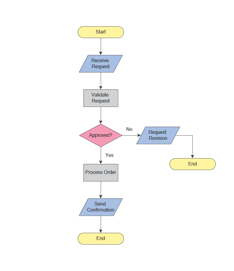
Picture: Flowchart Symbols: Meaning and Examples
Related Solution: