Yourdon and Coad Diagram
OOAD is simply an abbreviation for the term of “object-oriented analysis and design”, which is a very popular technical approach used for designing and analyzing any needed application, business or system in a way of applying the object-oriented programming. The mentioned approach involves the visual modelling throughout the life cycles development to foster better product quality and stakeholder communication.
OOAD in the modern software engineering is known to be best conducted in both incremental and iterative ways. The outputs of the OOAD activities, the analysis models for OOA as well as the design models for OOD are refined. Each software life cycle is usually divided up into at least a few stages: from abstract descriptions of the problem to designs to code as well as process of testing all the way to the deployment stage. The earliest stages of such process are analysis and design. The analysis phase is also known to be called as the "requirements acquisition".
In some approaches to the software development, such as the so-called “waterfall models”, the boundaries between each of the stages are meant to be sequential and rigid. The term "waterfall" itself is known to be coined for such methodologies in order to signify that the progress goes in one direction only. For example, once analysis is complete then its design can begin and it is not a usual thing for such situation to happen when a design issue requires a change in the analysis model or when, for instance, a coding issue requires some changes in design.
The alternative to the described “waterfall models” are the “iterative models”. The mentioned distinction was popularized by Barry Boehm while he was working on his Spiral Model trying to develop the software. In case of the “iterative models”, it is always possible to do work in a few different stages of the model in parallel. Thus, for example, it is always possible and acceptable to work on design, analysis and code on the same day having issues from one stage impact issues to another one. The software development is known to be a knowledge-intensive process and the things such as analysis cannot be realized without understanding the design issues as well as the coding issues affecting design.
The object-oriented model focuses on the re-usability as well as on modularity. The main goal of the object-oriented approach is to please the so-called "open-closed principle". A module is known to be “open” in case it supports extension. In case the module provides the standardized ways to add the new behaviours or to describe the new states. In the object-oriented paradigm it is often accomplished in a way of creating a new subclass of the existing class. Any module is known to be closed in case it has a well-defined stable interface that all of the other modules have to use and that limits the interaction as well as the potential errors that can be introduced into only one module by the changes in another.
Any software life cycle is known to be divided up into a few stages going from the abstract descriptions of the problem to design then to code, later — to the testing stage and later, finally, to the stage of deployment. The early stages of this process are stage of design and stage of analysis. There is a distinction between design and analysis which can sometimes be described as "how vs. what". In the analysis the developers are known to be working with the users as well as the domain experts try to define what system is supposed to do. The implementation details are expected to be totally or mostly ignored at this stage depending on the method itself.
The major difference between the object-oriented analysis and any other form of analysis is that by the object-oriented approach we can organize the requirements around objects, that integrate both data (states) and processes (behaviours), which were modelled after the real world objects which some particular system interacts with. In the so-called “traditional analysis methodologies”, the processes and data (the states and behaviours) are considered separately from each other. You can always visualize your data modelled by the Entity-Relationship diagram, for example, and the behaviours in the way of the flow or structure charts. To make any of the mentioned illustration you can always use ConceptDraw DIAGRAM software as well as any needed solution downloaded from another product of CS Odessa — ConceptDraw STORE.

Example 1. Data Flow Diagram (DFD) Solution in ConceptDraw STORE
The primary tasks in the OOA (object-oriented analysis) are to find the objects, to organize these objects, to describe the way how the objects interact with each other, to define the behaviour of the mentioned objects and so to define the internals of such objects. The common models which are used within OOA are object models and use cases. The object models are known to be those which are used for describing the class relations, such as a circle to be a subclass of a shape, for example, operations, properties and names of the major objects. The user-interface prototypes or mock-ups can also be created in order to help simplify the understanding. The use cases are known to be describing the scenarios for the standard domain functions which the system is expected to accomplish.
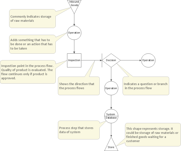
Example 2. Yourdon and Coad diagram — Order Process
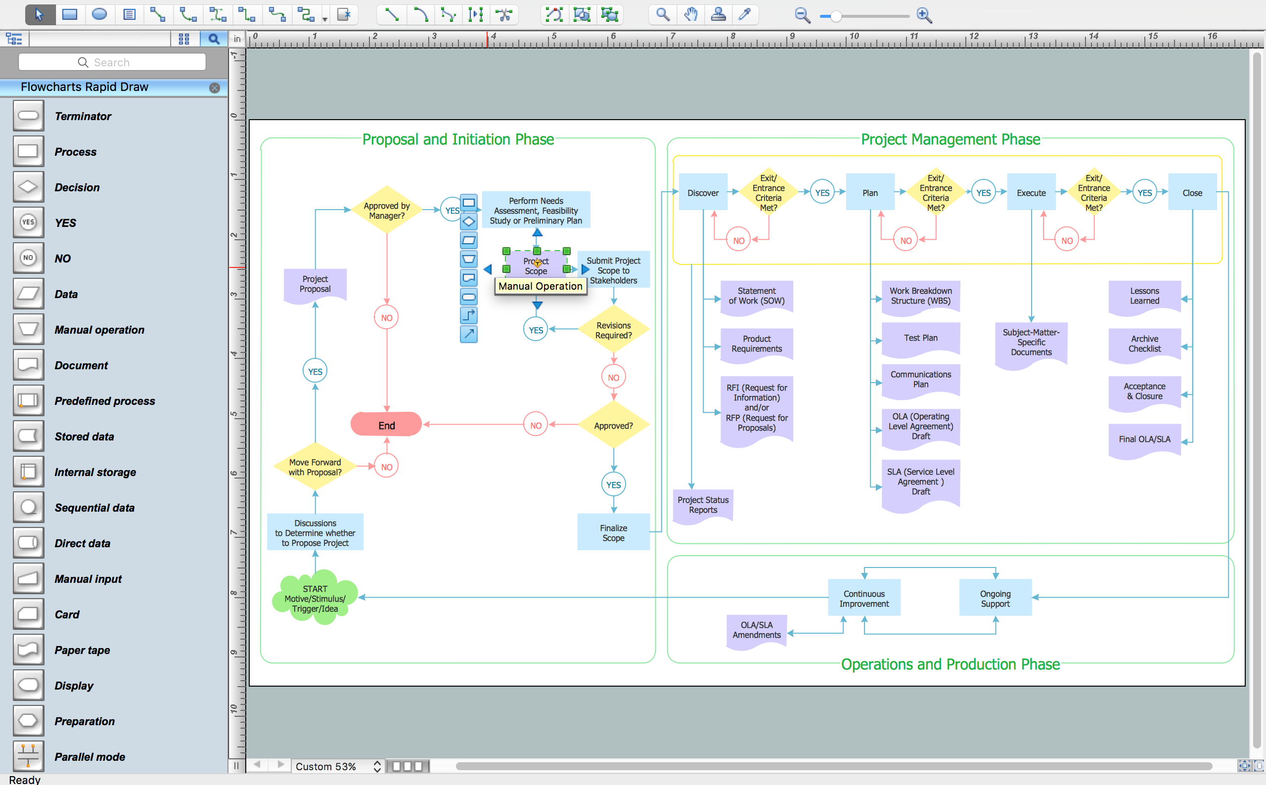
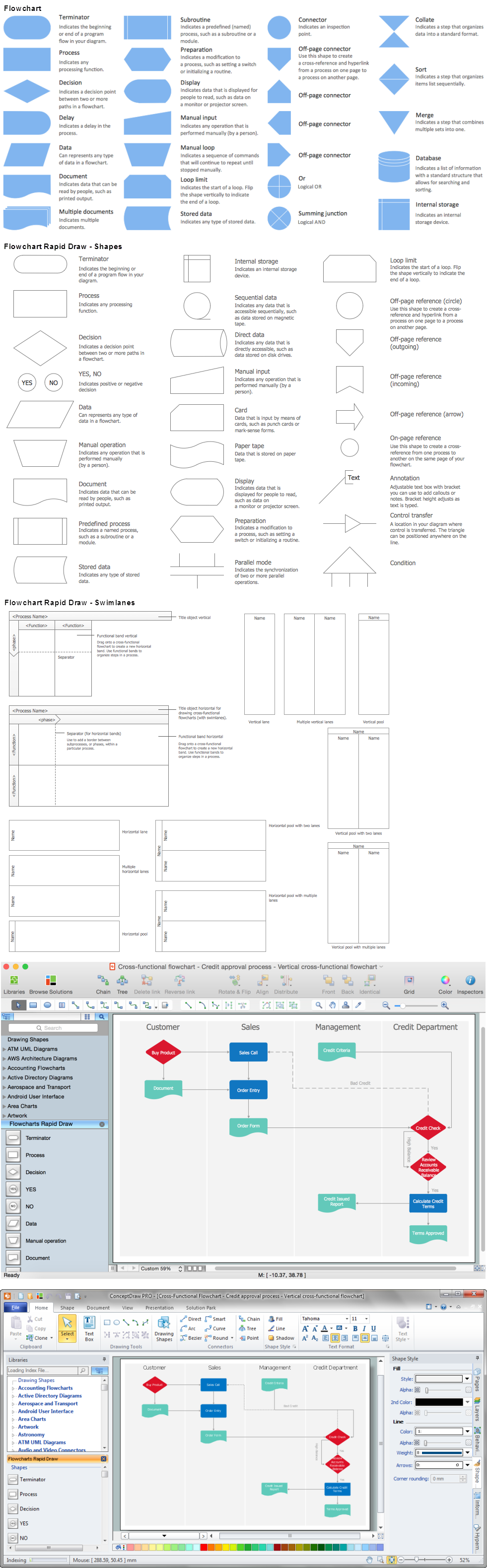
Being involved in the OOA as well as OOAD you might find it very useful to have an OOAD solution downloaded from the ConceptDraw STORE application to use while working in ConceptDraw DIAGRAM software creating any needed diagrams. Having all the needed tools can simplify your work with making the diagrams, such as the Yourdon and Coad ones. Peter Coad and Edward Yourdon developed the so-called “Coad/Yourdon method” used for the OOA. Object-oriented analysis and design (OOAD) is a popular technical approach for analyzing an application, designing the system or business in a way of applying the object-oriented paradigm. Being involved in such activity you may find ConceptDraw DIAGRAM a very useful professional tool for making any needed OOA diagrams.
ConceptDraw DIAGRAM is a perfect tool for:
- Designing and planning tasks such as:
- Developing Visualization Solutions
- Project Planning (Gantt Charts, Timelines, Project Schedules)
TEN RELATED HOW TO's:
Onion diagram is a type of circular diagram that consists of the core circle representing the product/solution and concentric circles around it, which dependent on the core and look like the cross sections of onion.
ConceptDraw DIAGRAM diagramming and vector drawing software supplied with Stakeholder Onion Diagrams Solution from the Management Area of ConceptDraw Solution Park is an ideal software for effective Onion diagram process design.
Picture: Onion Diagram Process Design
Related Solution:
The Workflow diagrams are the specialized type of flowcharts which allow to visualize any sorts of step-by-step processes. They are usually created as flowcharts, with objects that represent in a simple visual manner the steps in the process connected by arrows that indicate the next step. The ability easily create Workflow diagrams visually describing the tasks, documents associated with the tasks, people which are responsible for execution at each stage of workflow is made possible with Workflow Diagrams solution. This solution extends ConceptDraw DIAGRAM with a Workflow Diagram library that contains large collection of predesigned workflow flowchart symbols.
Picture: Workflow Flowchart Symbols
Related Solution:
Network Topology in communication networks, a topology is a usually schematic description of the arrangement of a network, including its nodes and connecting lines. There are two ways of defining network geometry: the physical topology and the logical topology.
Network Topology Mapper offers extensive drawing tools professional-looking network diagrams quickly and easily allowing you to clearly represent and communicate network architecture, topology, and design to engineers, stakeholders and end-users.
Picture: Network Topology Mapper
Related Solution:
Stakeholder analysis in conflict resolution, project management, and business administration, is the process of identifying the individuals or groups that are likely to affect or be affected by a proposed action, and sorting them according to their impact on the action and the impact the action will have on them.
Use the ConceptDraw DIAGRAM diagramming and vector drawing software enhanced with powerful tools of Stakeholder Onion Diagrams Solution from the Management Area of ConceptDraw Solution Park to easy and effectively visualize stakeholder analysis.
Picture: Visualize Stakeholder Analysis with Onion Diagram
Related Solution:
Times when you had difficulties in searching for an appropriate software depending on your OS, had passed. If you still look for a great software to create flowcharts on Mac, here is the answer. ConceptDraw Pro is a great tool for creating diagrams, with tons of samples, libraries and tutorials.
Making flowchart diagram is the best way to represent a process as a sequence of steps. Flowcharting provides a simple way of organizing and representing data so that even complex and detailed processes become clear. That is why using a flowchart software tool is proven to be an ideal for structure and share an information on process workflow structure. This flow chart was created to depict the steps of certification process. This flow chart was created using ConceptDraw DIAGRAM software for Apple OS X. The Rapid Draw technology was used to create this flow chart. ConceptDraw DIAGRAM also supports popular Apple OS X features such as Quick Look, Full-Screen Mode, Version Browsing and Autosave. You can export your multi-page diagrams to SVG or graphic formats such as TIFF, JPEG, PNG and PDF.
Picture: Create Flow Chart on Mac: The Comprehensive Guide
Related Solution:
In order to be successful, you have to promote your business on the market. One of the ways for planning this promotion is to create a social media DFD Flowchart which will contain all the details of your business strategy. Social media is a very influential tool, and it's a mistake to ignore it.
The following flowchart represents a best way to estimate social media posts, and gives a strategy of responses. This flowchart is designed in the format of cross-functional flowchart. With this format, we can divide the process into three distinct phases. This approach helps to generate well-considered and balanced response on social networks activities. Using ConceptDraw solution for Social Media Response, your reaction to social media posts will positively mirror the values and mission of your business.
Picture: How to Create a Social Media DFD Flowchart
Related Solution:
If you want to find a way to understand complex things in minutes, you should try to visualize data. One of the most useful tool for this is creating a flowchart, which is a diagram representing stages of some process in sequential order. There are so many possible uses of flowcharts and you can find tons of flow charts examples and predesigned templates on the Internet. Warehouse flowchart is often used for describing workflow and business process mapping. Using your imagination, you can simplify your job or daily routine with flowcharts.
Warehouse flowcharts are used to document product and information flow between sources of supply and consumers. The flowchart provides the staged guidance on how to manage each aspect of warehousing and describes such aspects as receiving of supplies; control of quality; shipment and storage and corresponding document flow. Warehouse flowchart, being actual is a good source of information. It indicates the stepwise way to complete the warehouse and inventory management process flow. Also it can be very useful for an inventory and audit procedures.
Picture: Flow Chart Example: Warehouse Flowchart
Related Solution:
This sample shows the Influence Diagram. It was created in ConceptDraw DIAGRAM diagramming and vector drawing software using the Basic Diagramming Solution from the Universal Diagramming area of ConceptDraw Solution Park.
Influence diagram represents the directed acyclic graph with three types of nodes and three types of arcs that connect the nodes. Decision node is drawn as a rectangle, Uncertainty node is drawn as an oval, Value node is drawn as an octagon.
Picture: Influence Diagram
Related Solution:
The vector stencils library Activity diagrams from the solution Rapid UML contains specific data modeling symbols for ConceptDraw DIAGRAM software.
Picture: Data Modeling Diagram
When thinking about the process of decision making, it's easy to imagine it as a pyramid. We will look at a three level pyramid model as an example. Operational decisions are first that come to mind, and it's the first level. Tactical and strategic decisions are the second and the third levels.
Pyramid (triangle) diagrams are used to show some hierarchical data. Because to the pyramid form of diagram, each diagram slice has a different width. The width of each segment depends on its hierarchical level.
The current image illustrates the model of information system types. Most graphically the model can be represented as a three level pyramid. The first level shows a system of transaction processing It is concentrated on operational tasks. The second level is devoted to tactical solutions of the information system management. And at least, the third level addresses strategy and represents the executive information system. This three level pyramid sample is supplied with the ConceptDraw Pyramid Diagrams solution from Marketing area of ConceptDraw Solution Park.
Picture: Pyramid Diagram
Related Solutions: