Data Modeling Diagram
What is a Data Modelling Diagram?
An abstract model that organizes some elements of data, standardizing the way they relate to one another as well as to properties of the real world entities, is called a “data model”. Such data model may specify that the data element representing a house can be composed of a number of other elements which, in turn, represent the color and size of this house as well as define its owner.
The term “data model” can be used in two senses. Time to time it refers to an abstract formalization of some objects or relationships, found in a particular application domain. These objects can be products, customers or orders found in some organization. Also it can refer to a set of concepts, which are used for defining the formalizations, such as attributes, entities, tables or relations. Thus, the data model of a banking application may be defined in a way of using the entity-relationship data model.
A data model identifies the structure of the data itself in detail. The data models can be specified in a so-called “data modeling notation”, which is often represented graphically. Such data model can sometimes be referred to as a “data structure”, especially in the context of the languages used in programming. Data models can be complemented by so-called “function models”, usually in the context of the so-called “enterprise models”. In order to simplify managing large quantities of structured as well as unstructured data, the information systems take place as it is their primary function.
Data models can describe the manipulation, the integrity aspects and the structure of some data stored in data management systems, e.g. “relational databases”. Such models typically do not describe any unstructured data, such as email messages, digital audio, pictures, word processing documents, video, etc. The main purpose of having the data models is to support the information systems development in a way of providing the definition as well as the format of some data. The problem is that interfaces and systems can cost more than they should in order to operate them, to build and to maintain. These systems may also constrain the business rather than to support it and a major cause is that the quality of the data models implemented in interfaces and systems is poor.
There are a few facts about the data models, which are known to be arbitrarily different for different systems, resulting to the complex interfaces being required between systems that share data. These interfaces can account for from 25% to 70% of the cost of the current systems. Usually the data simply cannot be shared electronically both with suppliers and customers for a reason of the structure and the meaning of data has not been standardized. As an example: the engineering design data and the engineering drawings for a process plant can still be sometimes exchanged on paper.
There are business rules, which can be often fixed in the structure of a data model, mentioning the specification of how these things are done in a particular place. The meaning of it is that the small changes in the way business is conducted can lead to the larger changes in the interfaces and the computer systems. The problem is that the entity types are often whether not identified or identified incorrectly, which can lead to the replication of the data itself or its structure, or its functionality, together with the attendant costs of that duplication in maintenance and development.
The reason for such problems occurring is a lack of the standards that can ensure that the data models can both be consistent and that they can meet all of the business needs which are required.
A so-called “data model explicitly” is meant to determine the structure of the data itself. The typical applications of the data models include the design of information systems, the database models and the enabling the exchange of data. The specification of the data models is usually determined in a data modeling language.
A “data model instance” may be one of the following kinds, which are “Physical data model”, “Logical data model” and “Conceptual data model”. The last one describes the semantics of a domain, which is a scope of the model. A conceptual schema is there to specify the kinds of propositions or facts, which can be expressed with a usage of the model. In this sense, it can define the allowed expressions in an artificial “language” using a scope, which is limited by the scope of the model. The “Physical data model”, mentioned above is the one describing the physical means by which data is stored, that is concerned with CPUs, partitions, tablespaces, etc. And the last, the “Logical data model” is the one describing the semantics, represented by a particular data manipulation technology, including the descriptions of columns and tables, XML tags and object oriented classes.
These three perspectives are relatively independent from each other. The storage technology can get changed without affecting either the conceptual or the logical model and the table as well as the column structure can be changed without even affecting the conceptual model. Taking it into consideration, the structures must remain consistent with the other model. The table/column type of displaying may differ from a direct translation of the entity attributes and classes, although it must carry out the objectives of the conceptual entity class structure.
Considering all of the nuances mentioned above you may decide to create your own data modeling diagram using one of the most convenient in use applications — ConceptDraw DIAGRAM. This software allows making any needed diagram, including the discussed one, within only a short period of time, having the needed solutions from ConceptDraw STORE as well as from this site. Thus, creating data modeling diagram, you may find the “Rapid UML solution” from the “Software Development area” of ConceptDraw Solution Park on this site very useful. Having the vector stencils library named “Activity diagrams” from this solution can simplify your work of drawing the needed diagram using the ConceptDraw DIAGRAM software.

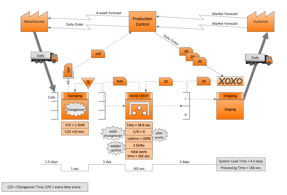
Example 1. Data Modeling Diagrams Solutions
Use the Rapid UML solution to draw UML and SysML activity diagrams for your business documents, presentations and websites.

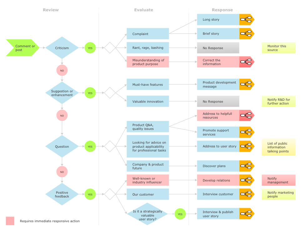
Example 2. Data Modeling SysML Activity Diagram
This example illustrates the usage of SysML activity diagrams for data modeling.
ConceptDraw DIAGRAM is a perfect tool for:
- Designing and planning tasks such as:
- Jacobson Use Cases Diagram
- SSADMN Diagram
- Yourdon and Coad Diagram
- Command OLE Diagram
- Block Diagrams
- SysML Diagram
- Chen RED Diagram
- Martin RED Diagram
- IDEF0 Diagram
- Booch OOD Diagram
- Gane Sarson Diagram
- Memory Object Diagram
- Data Flow Diagram
- FlowCharts
- Graphic User Interface (GUI)
- UML Diagram
- Program Structure Diagrams
- ORM Diagram
- Developing Visualization Solutions
- Project Planning (Gantt Charts, Timelines, Project Schedules)