Data Flow Diagram Model
|
DFD is an acronym for “data flow diagram”, being a graphical representation of the data flow through some information system in a way of modelling its process aspects, being often used as a step for creating some overview of the mentioned system, but usually not a detailed one. Data flow diagrams can also be used for visualizing some data processing used in the so called “structured design”. Each of the data flow diagrams can show the way each type of information can be input to as well as output from a system. It can also show in what way data can advance through this system. It’s very important to mention the exact place where this data is stored, not showing information about the timing of some process or about the processes operating in parallel or in sequence. “Data flow diagram” and “Flow Chart” are, if not identical, then very similar terms, and they both can be also used for the same purpose of illustrating a flow of some data. Flow diagrams are: Data Flows Diagrams, Entity Relationship Diagrams, Unified Modelling Language diagrams, Windows and Macintosh Graphics User Interface design diagrams, diagrams created with a usage of Structured Systems Analysis and Design Method (SSADM), and other. One of the most popular flow diagram is a data flow diagram, or DFD, used for representing of data flow in an information system graphically. With help of this diagram, you can always illustrate a system overview in outline using ConceptDraw DIAGRAM as well as the needed solution among those, which can be found in ConceptDraw STORE application. As it was mentioned before, any data flow diagram, used for the visualizing data processing in a structured design, can be created in ConceptDraw DIAGRAM software, which users can make any other needed diagram any time they want within only a short period of time having the solutions extended with the pre-made templates and samples of such drawings. Data flow diagrams are widely used nowadays for a reason: with help of these diagrams you can always show what kind of information can be input to as well as output from some system as well as the way this data can advance via such system. With help of “DFD” you can also show where data can be stored and with help of ConceptDraw DIAGRAM drawing application you can do it within only a few hours or even minutes, if you have the stencil libraries and examples of such diagrams from the “solutions”, developed in order to simplify this task. Data flow diagram is also known “bubble chart”. One of such diagrams is known to be called a “context-level data flow” one. This context-level data flow diagram includes a “Level 1 DFD”, which can be created for a reason of representing some of the system’s details, that are being modelled. The “Level 1 data flow diagrams” are used for showing the way some system is (or can be) divided into the smaller so called “sub-systems”, illustrating the way, in what these “sub-systems” deal with the “data flows”. If you need to identify the internal data stores, you can simply make any needed data flow diagram using ConceptDraw DIAGRAM data flow diagramming software, as such type of diagrams is one of the three perspectives of the “SSADM”. The sponsor of the project as well as the end user, mentioned on the diagram, can be consulted at all the stages of a system's evolution. To conveniently track the mentioned “evolution”, DFD would be the best diagram for such purpose, as using this type of diagram as a simple way of representing the operating system is one of the best possible options. And you can also mention how the plans for the system can be implemented within the same drawing. Data flow diagrams can be used to provide the end user with all the needed information about the inputting data. It can also be useful for mentioning the information about the system, which can be developed both on the analysis and design stages. There notations you can use for creating any needed data flow diagrams can be two - the “Yourdon and Coad” and the “Gane and Sarson” one. These notations can be used for defining different visual representations of the data flows, external entities, data stores and the other completely different processes. The so called “Logical Data Flow Diagram” can be also created with help of ConceptDraw DIAGRAM software, as it is useful for capturing the data flows, which are usually very necessary for the system to operate. To describe the needed processes as well we the data required, a DFD can be also helpful. Mentioning another type of DFD, it’s important not to forget the “Physical Data Flow Diagram” (also known as “Current Physical Data flow diagram”), used for the purpose of showing the way in what a system is implemented right now. In general, “Data flow diagram” is well known as a great tool for representing any needed data flow in a system. Being a part of the “Structured Systems Analysis and Design Methodology”, such diagram may be consisted of the different components: processes and functions. All the main DFD elements are processes, external entities, data store and data flow.
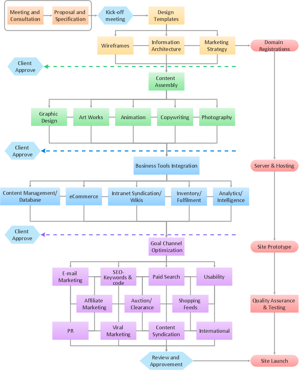
Example 1. Data Flow Diagram Model solution This example shows production process of a traditional small enterprise. DFD diagrams are a useful way of visualizing a system and analyzing what it will accomplish. |


Example 2. DFD — Model of Small Traditional Production Enterprise
If you want to make any DFD, then everything you need to do is to download ConceptDraw DIAGRAM software as well as the needed solution from “ConceptDraw STORE” application or from this site. Thus, having “Data Flow Diagrams Solution” can simplify your work with drawing all the needed data flow diagrams and models within both notations, including the “Yourdon – de Marco”, as this notation can help to illustrate the data flow diagram objects, being interpreted in a way of processes transform the input data flows into the output ones and data depositories serve them only for keeping the “ingoing” data, without changing them.
The “Object Library” full of the design elements, that can be used in your drawings, can be found in the “Data Flow Diagram Solution” from ConceptDraw STORE application to help you to represent any data storage, objects, data flows, processes and data flow entities.
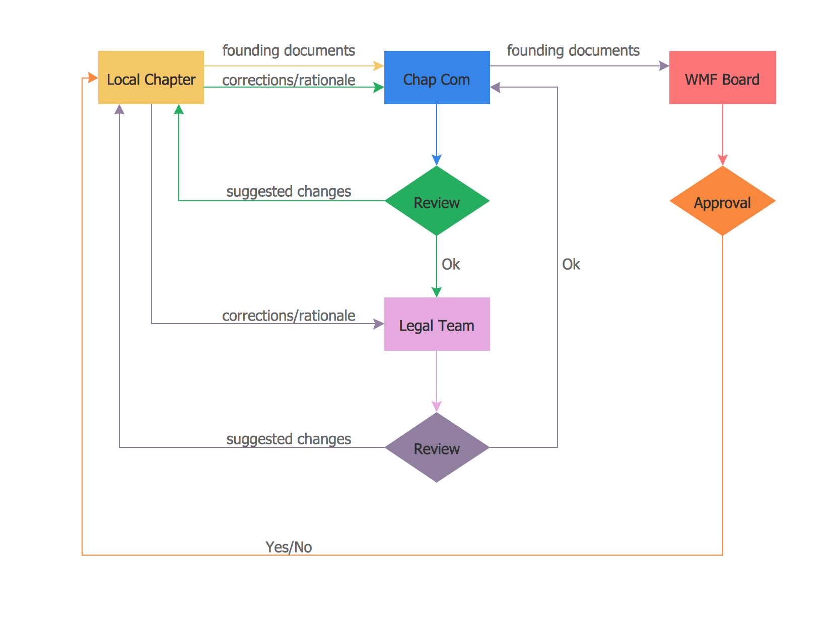
Data Flow Diagrams Sample: