Software Engineering
There are lots of fields of business activity where both products of CS Odessa — ConceptDraw DIAGRAM and ConceptDraw STORE — can be applied to. One of the most challenging ones is engineering, types of which are known to be varying a lot.
Engineering itself is the application of such studies as science, mathematics, economics, social knowledge, practical knowledge and empirical evidence used for inventing, innovating, designing, building, maintaining, doing research as well as improving the structures, tools, machines, systems, materials, components, processes, organizations and solutions. The discipline of engineering is known to be encompassing a wide range of more specialized fields of engineering. Each of them has a more specific emphasis on some definite areas of applied science, applied mathematics, and other types of application.
The term engineering itself is known to be derived from the Latin word “ingenium”, which means "cleverness", as well as another word — ingeniare, which means "to devise, contrive". Engineers from all over the world apply both mathematics and sciences (e.g., physics) in order to find the needed novel solutions to some particular problems. They may also work on improving the already existing solutions. Engineers are now in a very high demand as they have a proficient knowledge of relevant sciences which may help support different design projects.
In case there are multiple solutions that exist, engineers weigh each of the design choices that are based on their merit, choosing the best solution that matches all the requirements. The unique and crucial task of any engineer is to understand, to identify and to interpret the constraints on a design in terms of yielding some successful result. Usually, it is known to be insufficient to build some technically successful product.
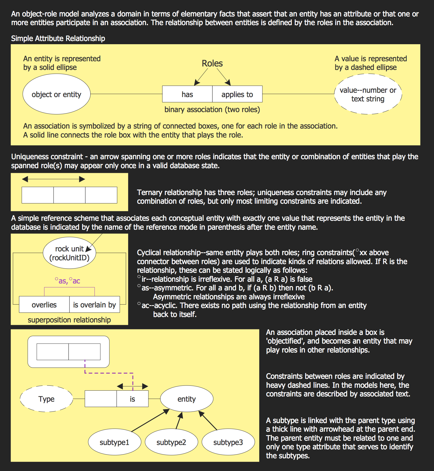
Example 1. Software Engineering — Object-Role Model Overview
The previously mentioned constraints may include physical, technical or imaginative limitations, available resources, flexibility for some future additions and modifications, as well as other factors, such as requirements for safety, cost, marketability, serviceability and productivity. Knowing the constraints well, the engineers are known to be the right specialists for deriving all the needed specifications for the limits within which some viable system or object may be operated after it is produced.
Nowadays, both computers and software play more and more increasingly important role. As well as the typical business application software, there are many computer aided applications (also known as the computer-aided technologies) that can be used specifically for engineering. Computers can be used in order to generate different models of fundamental physical processes. Such processes can be solved by using some particular numerical methods.
Recently, the usage of different computer applications and computer software to aid the development of goods has come to be known as the so-called “product lifecycle management” (PLM).
In industry, PLM is known to be the process of managing all the lifecycle of a product. It involves its inception, engineering design and manufacture, as well as servicing and disposal of different manufactured products. PLM integrates both people and data, business systems and processes, providing the needed product information fundamental for companies as well as their extended enterprise.
Computer software is one of so many parts of the entire computer system that is known to be consisting of either data or computer instructions. In software engineering (as well as in computer science), computer software is simply all the information that needs to be processed by computer programs, data and computer systems. Computer software includes libraries, computer programs, etc., requiring computer hardware, not being able to be used on its own.
To develop a software, an object-role modeling (ORM) can be used for modelling the semantics of a universe of discourse. Any object-role model is known to be using the particular graphical symbols that are all expected to be based on first order predicate logic and set theory for enabling the modeler to create some unambiguous definition of an arbitrary universe of discourse.
The predicates of an ORM Model are known to be attribute-free, lending themselves to the design and analysis of graph database models. ORM diagrams are often used in software engineering field of business activity and they can be always created with the help of ConceptDraw DIAGRAM either using the basic stencil libraries or the ones that the new ones the Object-Role Modeling (ORM) solution provides.

Example 2. Software Engineering solution
For database modeling, such as graph databases and/or relational databases modelling, for business rules modeling, for XML-Schemas modeling, data warehouses modeling or for web forms modeling — it does not matter what your reasons for creating the ORM diagrams are, you can always make any needed ORM-related drawings with the aid of ConceptDraw DIAGRAM and ConceptDraw STORE that can simplify your work by providing the so-called “Object-Role Modeling (ORM) solution” as a great ORM diagram drawing tool, including the ORM-related vector stencils libraries, ORM diagram samples and templates as well as learning media.

