Yourdon and Coad Diagram

Data Flow Diagram Symbols. DFD Library

Software Diagram Examples and Templates

Software Development area of ConceptDraw Solution Park provides 5 solutions:
Data Flow Diagrams, Entity-Relationship Diagram (ERD), Graphic User Interface, IDEFO Diagrams, Rapid UML.
"Data flow diagrams are one of the three essential perspectives of the structured-systems analysis and design method SSADM. The sponsor of a project and the end users will need to be briefed and consulted throughout all stages of a system's evolution. With a data flow diagram, users are able to visualize how the system will operate, what the system will accomplish, and how the system will be implemented. The old system's dataflow diagrams can be drawn up and compared with the new system's data flow diagrams to draw comparisons to implement a more efficient system. Data flow diagrams can be used to provide the end user with a physical idea of where the data they input ultimately has an effect upon the structure of the whole system from order to dispatch to report. How any system is developed can be determined through a data flow diagram model.
In the course of developing a set of levelled data flow diagrams the analyst/ designers is forced to address how the system may be decomposed into component sub-systems, and to identify the transaction data in the data model.
Data flow diagrams can be used in both Analysis and Design phase of the SDLC.
There are different notations to draw data flow diagrams (Yourdon & Coad and Gane & Sarson), defining different visual representations for processes, data stores, data flow, and external entities." [Data flow diagram. Wikipedia]
The DFD (Yourdon and Coad notation) example "Process of account receivable" was created using the ConceptDraw PRO diagramming and vector drawing software extended with the Data Flow Diagrams solution from the Software Development area of ConceptDraw Solution Park.
Data Flow Diagram

The vector stencils library "DFD, Yourdon and Coad notation" contains 22 DFD elements.
Use it for drawing data flow diagrams (DFD) using Yourdon/ DeMarco notation in the ConceptDraw PRO diagramming and vector drawing software extended with the Data Flow Diagrams solution from the Software Development area of ConceptDraw Solution Park.
Use it for drawing data flow diagrams (DFD) using Yourdon/ DeMarco notation in the ConceptDraw PRO diagramming and vector drawing software extended with the Data Flow Diagrams solution from the Software Development area of ConceptDraw Solution Park.
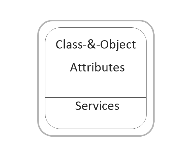
Class and object
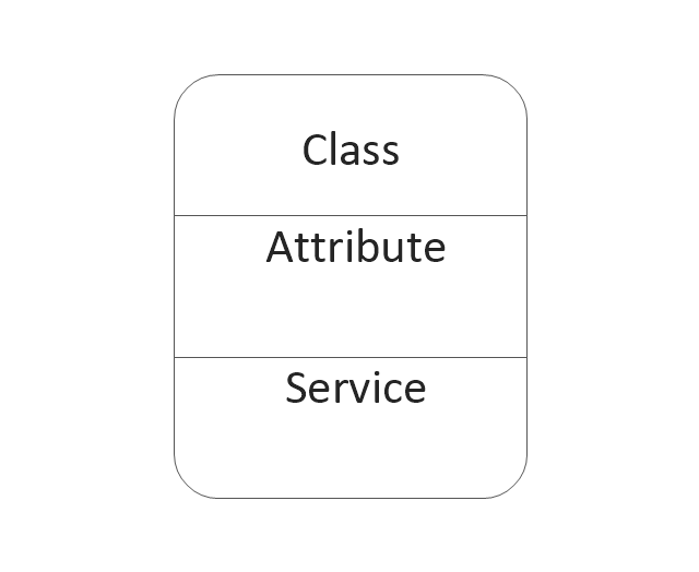
Class
Object state

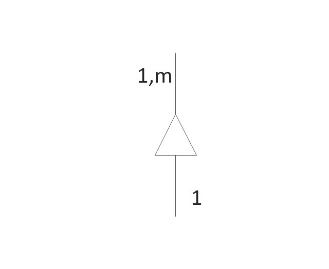
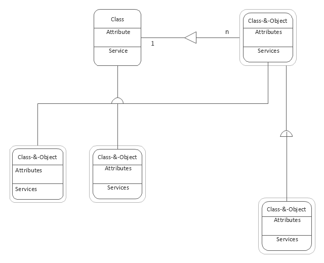
Generalization and specialization structure

Whole-part structure
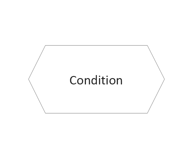
Condition
Loop
External interactor
Data process
Multiple process
State
Multi-state
Stop state

Stop state2
Process
Process (offset)
-dfd,-yourdon-and-coad-notation---vector-stencils-library.png--diagram-flowchart-example.png)
Center to center

Center to center #2

Loop on center
Data store
Instance

Message

Data Flow Diagram Examples

 Data Flow Diagrams (DFD)
Data Flow Diagrams solution extends ConceptDraw DIAGRAM software with templates, samples and libraries of vector stencils for drawing the data flow diagrams (DFD).
Data Flow Diagram

UML Class Diagram. Design Elements

Use this template to create your DFD by Yourdon and Coad notation using the ConceptDraw PRO diagramming and vector drawing software extended with the Data Flow Diagrams solution from the Software Development area of ConceptDraw Solution Park.
DFD template
Data Flow Diagram (DFD)
 *")
IDEF0 Diagram

Data Flow Diagrams

Design Element: Crows Foot for Entity Relationship Diagram - ERD

Time - Design Elements

Data Flow Diagrams

Data Flow Diagram Software

ConceptDraw DIAGRAM is a powerful Data Flow Diagram Software thanks to the Data Flow Diagrams solution from the Software Development area of ConceptDraw Solution Park.
You can use the predesigned DFD vector objects that are grouped in 3 libraries of Data Flow Diagrams solution: Data Flow Diagrams Library; Gane-Sarson Notation Library; Yourdon and Coad Notation Library.
UML Activity Diagram. Design Elements


Software Diagrams

ConceptDraw DIAGRAM is a perfect tool for Designing and planning tasks; Developing Visualization Solutions; Project Planning (Gantt Charts, Timelines, Project Schedules).
UML Class Diagrams. Diagramming Software for Design UML Diagrams

Use ConceptDraw DIAGRAM with UML class diagram templates, samples and stencil library from Rapid UML solution to show the classes of system, their attributes, operations or methods, and the relationships among the classes.
- Yourdon and Coad Diagram | DFD, Yourdon and Coad notation ...
- DFD, Yourdon and Coad notation - Template
- Yourdon and Coad Diagram | Data Flow Diagram Symbols. DFD ...
- Yourdon and Coad Diagram | ConceptDraw DIAGRAM DFD ...
- Yourdon and Coad Diagram | Coad / Yourdon's Object-Oriented ...
- Yourdon and Coad Diagram | OOSE Method | Professionally ...
- Yourdon and Coad Diagram | OOSE Method | Coad / Yourdon's ...
- DFD, Yourdon and Coad notation - Vector stencils library | DFD ...
- Coad / Yourdon's Object-Oriented Analysis model | Yourdon and ...
- Coad / Yourdon's Object-Oriented Analysis model | ConceptDraw ...
- DFD, Yourdon and Coad notation - Vector stencils library | Data ...
- DFD, Yourdon and Coad notation - Vector stencils library ...
- DFD, Yourdon and Coad notation - Template
- Booch OOD Diagram | Yourdon and Coad Diagram | Software ...
- Data flow diagram - Template | DFD, Yourdon and Coad notation ...
- Coad / Yourdon's Object-Oriented Analysis model | Yourdon and ...
- Booch OOD Diagram | Yourdon and Coad Diagram | Software ...
- Data structure diagram with ConceptDraw DIAGRAM | Yourdon and ...
- DFD, Yourdon and Coad notation - Vector stencils library | Coad ...
- Data Flow Diagrams (DFD) | Coad Yourdon Methodology Ppt
- ERD | Entity Relationship Diagrams, ERD Software for Mac and Win
- Flowchart | Basic Flowchart Symbols and Meaning
- Flowchart | Flowchart Design - Symbols, Shapes, Stencils and Icons
- Flowchart | Flow Chart Symbols
- Electrical | Electrical Drawing - Wiring and Circuits Schematics
- Flowchart | Common Flowchart Symbols
- Flowchart | Common Flowchart Symbols