The vector stencils library "DFD, Yourdon and Coad notation" contains 22 DFD elements.
Use it for drawing data flow diagrams (DFD) using Yourdon/ DeMarco notation in the ConceptDraw PRO diagramming and vector drawing software extended with the Data Flow Diagrams solution from the Software Development area of ConceptDraw Solution Park.
Use it for drawing data flow diagrams (DFD) using Yourdon/ DeMarco notation in the ConceptDraw PRO diagramming and vector drawing software extended with the Data Flow Diagrams solution from the Software Development area of ConceptDraw Solution Park.
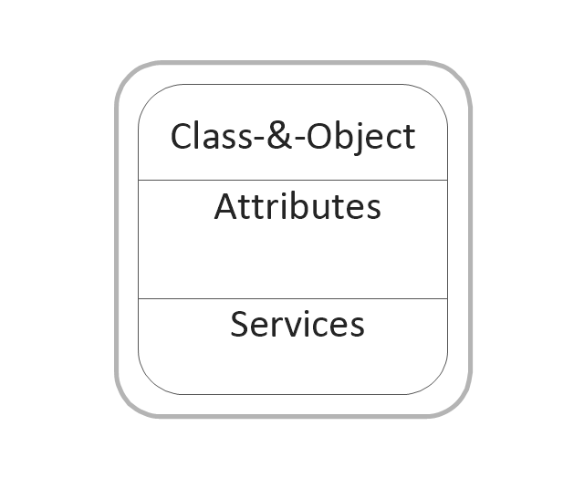
Class and object
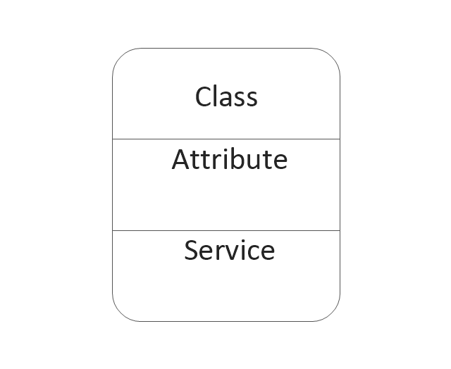
Class
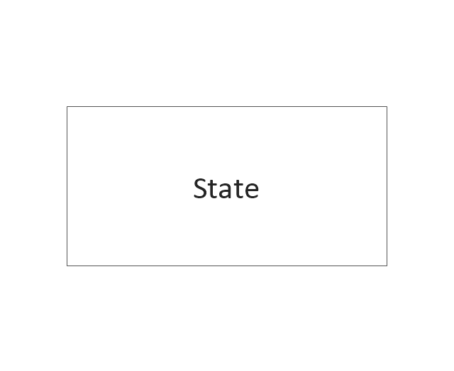
Object state
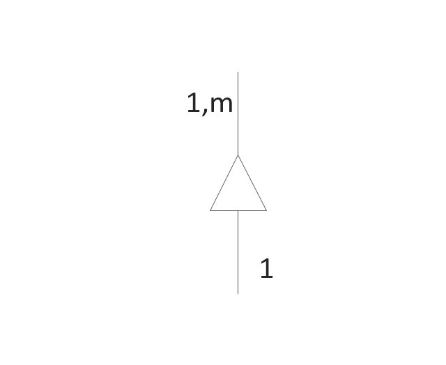
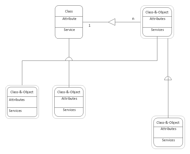
Generalization and specialization structure

Whole-part structure
Condition
Loop
External interactor
Data process
Multiple process
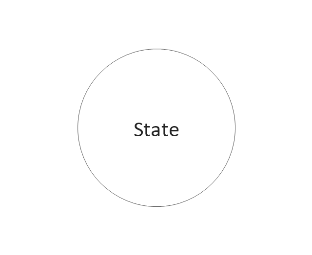
State
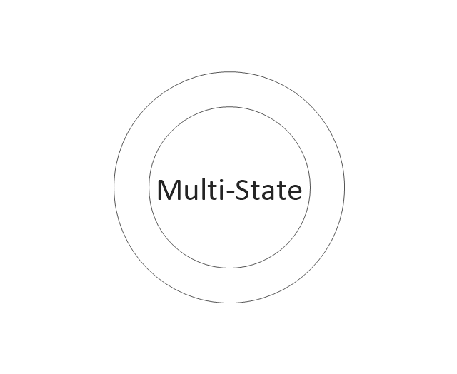
Multi-state
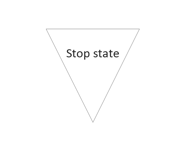
Stop state

Stop state2
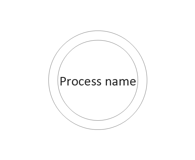
Process
Process (offset)
-dfd,-yourdon-and-coad-notation---vector-stencils-library.png--diagram-flowchart-example.png)
Center to center

Center to center #2

Loop on center
Data store
Instance

Message

Software Diagram Examples and Templates

Yourdon and Coad Diagram

UML Class Diagram. Design Elements

Time - Design Elements

Use this template to create your DFD by Yourdon and Coad notation using the ConceptDraw PRO diagramming and vector drawing software extended with the Data Flow Diagrams solution from the Software Development area of ConceptDraw Solution Park.
DFD template
Building Drawing. Design Element — Plumbing

Object-Oriented Design

Design Element: Crows Foot for Entity Relationship Diagram - ERD

UML Class Diagrams. Diagramming Software for Design UML Diagrams


Using Both Wired and Wireless Connections

Building Networks

UML Activity Diagram. Design Elements

IDEF0 Diagram

Data Flow Diagram Symbols. DFD Library

Basic Flowchart Images. Flowchart Examples

Context Diagram Template

This template shows the Context Diagram. It was created in ConceptDraw DIAGRAM diagramming and vector drawing software using the Block Diagrams Solution from the “Diagrams” area of ConceptDraw Solution Park. The context diagram graphically identifies the system. external factors, and relations between them. It’s a high level view of the system. The context diagrams are widely used in software engineering and systems engineering for designing the systems that process the information.
 Data Flow Diagrams (DFD)
Data Flow Diagrams solution extends ConceptDraw DIAGRAM software with templates, samples and libraries of vector stencils for drawing the data flow diagrams (DFD).
Data Flow Diagram (DFD)
 *")
Flowchart design. Flowchart symbols, shapes, stencils and icons


- DFD, Yourdon and Coad notation - Template
- Yourdon and Coad Diagram | ConceptDraw DIAGRAM DFD ...
- DFD, Yourdon and Coad notation - Vector stencils library | DFD ...
- DFD, Yourdon and Coad notation - Vector stencils library ...
- Yourdon and Coad Diagram | Data Flow Diagram Symbols. DFD ...
- DFD, Yourdon and Coad notation - Vector stencils library | Data ...
- DFD, Yourdon and Coad notation - Template
- DFD, Yourdon and Coad notation - Vector stencils library | Coad ...
- Data flow diagram - Template | DFD, Yourdon and Coad notation ...
- Coad / Yourdon's Object-Oriented Analysis model | ConceptDraw ...
- Coad / Yourdon's Object-Oriented Analysis model | Yourdon and ...
- Yourdon and Coad Diagram | Coad / Yourdon's Object-Oriented ...
- Yourdon and Coad Diagram | OOSE Method | Coad / Yourdon's ...
- Yourdon and Coad Diagram | OOSE Method | Professionally ...
- Booch OOD Diagram | Yourdon and Coad Diagram | Software ...
- Design elements - UML class diagrams | DFD, Yourdon and Coad ...
- DFD, Yourdon and Coad notation - Template | DFD, Gane-Sarson ...
- Booch OOD Diagram | Yourdon and Coad Diagram | Software ...
- Coad / Yourdon's Object-Oriented Analysis model | Yourdon and ...