State Diagram Example — Online Store

This sample shows the work of the online store and can be used for the understanding of the online shopping processes, for projection and creating of the online store.
UML State Machine Diagram.Design Elements

ConceptDraw has 393 vector stencils in the 13 libraries that helps you to start using software for designing your own UML Diagrams. You can use the appropriate stencils of UML notation from UML State Machine library.
The vector stencils library "UML state machine diagrams" contains 35 symbols for the ConceptDraw PRO diagramming and vector drawing software.
"The state diagram in the Unified Modeling Language is essentially a Harel statechart with standardized notation, which can describe many systems, from computer programs to business processes. In UML 2 the name has been changed to State Machine Diagram. The following are the basic notational elements that can be used to make up a diagram:
(1) Filled circle, pointing to the initial state.
(2) Hollow circle containing a smaller filled circle, indicating the final state (if any).
(3) Rounded rectangle, denoting a state. Top of the rectangle contains a name of the state. Can contain a horizontal line in the middle, below which the activities that are done in that state are indicated.
(4) Arrow, denoting transition. The name of the event (if any) causing this transition labels the arrow body. A guard expression may be added before a "/ " and enclosed in square-brackets ( eventName[guardExpression] ), denoting that this expression must be true for the transition to take place. If an action is performed during this transition, it is added to the label following a "/ " ( eventName[guardExpression]/ action ).
(5) Thick horizontal line with either x>1 lines entering and 1 line leaving or 1 line entering and x>1 lines leaving. These denote join/ fork, respectively." [State diagram (UML). Wikipedia]
The example "Design elements - UML state machine diagrams" is included in the Rapid UML solution from the Software Development area of ConceptDraw Solution Park.
UML state machine diagram symbols

Diagramming Software for Design UML State Machine Diagrams


State Machine Diagram

The vector stencils library "Bank UML state machine diagram" contains 21 shapes for drawing UML state machine diagrams.
Use it for object-oriented modeling of your bank information system.
"The state diagram in the Unified Modeling Language is essentially a Harel statechart with standardized notation, which can describe many systems, from computer programs to business processes. In UML 2 the name has been changed to State Machine Diagram. The following are the basic notational elements that can be used to make up a diagram:
* Filled circle, pointing to the initial state.
* Hollow circle containing a smaller filled circle, indicating the final state (if any).
* Rounded rectangle, denoting a state. Top of the rectangle contains a name of the state. Can contain a horizontal line in the middle, below which the activities that are done in that state are indicated.
* Arrow, denoting transition. The name of the event (if any) causing this transition labels the arrow body. A guard expression may be added before a "/ " and enclosed in square-brackets ( eventName[guardExpression] ), denoting that this expression must be true for the transition to take place. If an action is performed during this transition, it is added to the label following a "/ " ( eventName[guardExpression]/ action ).
* Thick horizontal line with either x>1 lines entering and 1 line leaving or 1 line entering and x>1 lines leaving. These denote join/ fork, respectively." [State machine diagram. Wikipedia]
This example of UML state machine diagram symbols for the ConceptDraw PRO diagramming and vector drawing software is included in the ATM UML Diagrams solution from the Software Development area of ConceptDraw Solution Park.
UML state machine diagram symbols

ConceptDraw DIAGRAM UML Diagrams with ConceptDraw DIAGRAM

UML Diagram for Mac

UML Diagram

Create unified modeling language (UML) diagrams with ConceptDraw.
Design Elements for UML Diagrams

UML Class Diagrams. Diagramming Software for Design UML Diagrams

Use ConceptDraw DIAGRAM with UML class diagram templates, samples and stencil library from Rapid UML solution to show the classes of system, their attributes, operations or methods, and the relationships among the classes.
"State machine diagram is a behavior diagram which shows discrete behavior of a part of designed system through finite state transitions. State machine diagrams can also be used to express the usage protocol of part of a system. Two kinds of state machines defined in UML 2.4 are:
(1) behavioral state machine, and
(2) protocol state machine.
The following nodes and edges are typically drawn in state machine diagram: behavioral state, behavioral transition, protocol state, protocol transition, different pseudostates. ...
Behavioral state machine is specialization of behavior and is used to specify discrete behavior of a part of designed system through finite state transitions. The state machine formalism used in this case is an object-based variant of Harel statecharts.
Behavior is modeled as a traversal of a graph of state nodes connected with transitions. Transitions are triggered by the dispatching of series of events. During the traversal, the state machine could also execute some activities. ...
Protocol state machine is a specialization of behavioral state machine and is used to express usage protocol or lifecycle of a classifier. It specifies which operations of the classifier can be called in which state and under which condition, thus specifying the allowed call sequences on the classifier’s operations. Protocol state machines express the legal transitions that a classifier can trigger." [uml-diagrams.org/ state-machine-diagrams.html]
The template "UML state machine diagram" for the ConceptDraw PRO diagramming and vector drawing software is included in the Rapid UML solution from the Software Development area of ConceptDraw Solution Park.
www.conceptdraw.com/ solution-park/ software-uml
UML state machine diagram

UML Interaction Overview Diagram. Design Elements

ConceptDraw has 393 vector stencils in the 13 libraries that helps you to start using software for designing your own UML Diagrams. You can use the appropriate stencils of UML notation from UML Interaction Overview library.
UML Process Diagram Example

UML Notation

Two types of diagrams are used in UML: Structure Diagrams and Behavior Diagrams. Behavior Diagrams represent the processes proceeding in a modeled environment. Structure Diagrams represent the elements that compose the system.
UML Class Diagram Example - Medical Shop

This sample shows the work of the medical shop and is used at the creation of the medical shop or pharmacy project, for understanding the process of shopping in the medical shop, for keeping purchases, for medical supplies.
"RT-middleware (Robotics Technology Middleware) is a common platform standards for Robots based on the distributed object technology. RT-middleware supports the construction of various networked robotic systems by the integration of various network enabled robotic elements called RT-Components. The specification standard of the RT-component is discussed / defined by the Object Management Group (OMG). ...
In the RT-middleware, robotics elements, such as actuators, are regarded as RT-components, and the whole robotic system is constructed by connecting those RT-components. This distributed architecture helps developers to re-use the robotic elements, and boosts the reliability of the robotic system.
Each RT-component has port as an endpoint for communicating other RT-components. Every port has its type and the ports which have the same type can be connected each other.
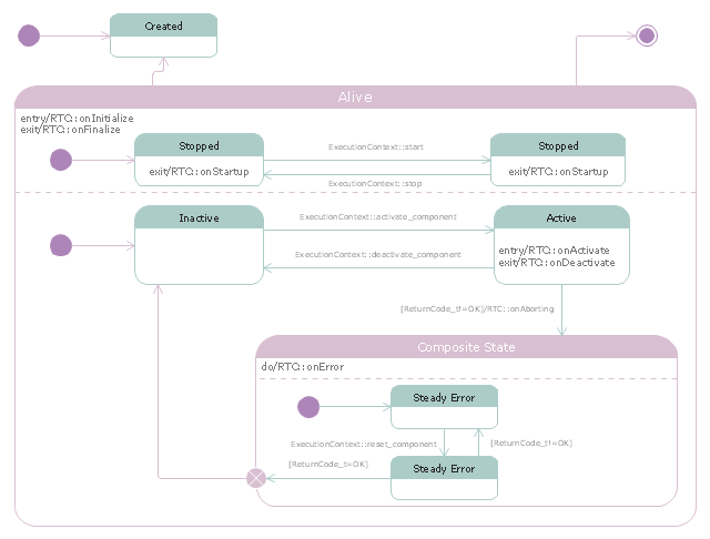
RT-components also has its state, so the RT-components behaves as state machines. The states that RT-components can have are CREATED, INACTIVE, ACTIVE, and ERROR, and the states and behaviors are controlled by the execution-context. If developers want to change the behavior of their RT-components, the execution-context can be replaced at run-time." [RT middleware. Wikipedia]
The UML state machine diagram example "State transitions of RT-component" was created using the ConceptDraw PRO diagramming and vector drawing software extended with the Rapid UML solution from the Software Development area of ConceptDraw Solution Park.
In the RT-middleware, robotics elements, such as actuators, are regarded as RT-components, and the whole robotic system is constructed by connecting those RT-components. This distributed architecture helps developers to re-use the robotic elements, and boosts the reliability of the robotic system.
Each RT-component has port as an endpoint for communicating other RT-components. Every port has its type and the ports which have the same type can be connected each other.
RT-components also has its state, so the RT-components behaves as state machines. The states that RT-components can have are CREATED, INACTIVE, ACTIVE, and ERROR, and the states and behaviors are controlled by the execution-context. If developers want to change the behavior of their RT-components, the execution-context can be replaced at run-time." [RT middleware. Wikipedia]
The UML state machine diagram example "State transitions of RT-component" was created using the ConceptDraw PRO diagramming and vector drawing software extended with the Rapid UML solution from the Software Development area of ConceptDraw Solution Park.
UML state machine diagram
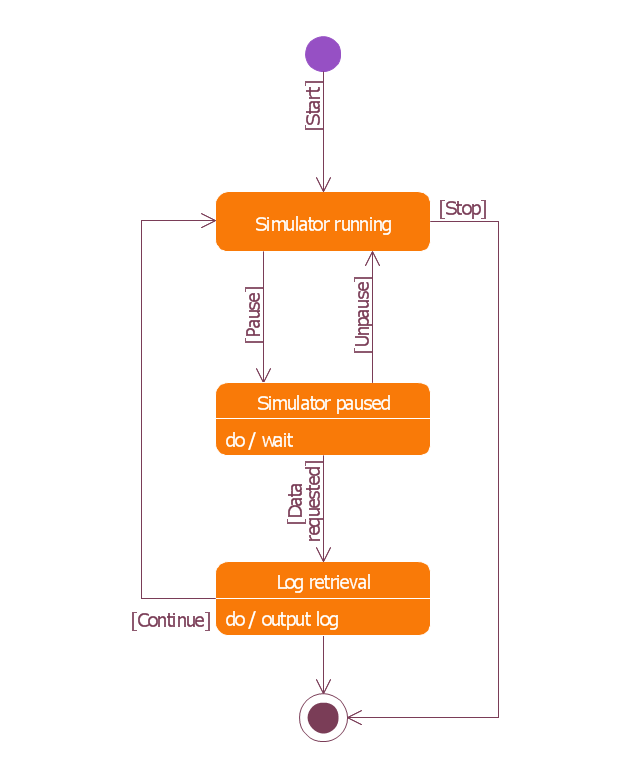
This example was redesigned from the Wikimedia Commons file: UML state diagram.png.
[commons.wikimedia.org/ wiki/ File:UML_ state_ diagram.png]
This file is licensed under the Creative Commons Attribution-Share Alike 3.0 Unported license. [creativecommons.org/ licenses/ by-sa/ 3.0/ deed.en]
"The StateMachine package defines a set of concepts that can be used for modeling discrete behavior through finite state transition systems. The state machine represents behavior as the state history of an object in terms of its transitions and states. The activities that are invoked during the transition, entry, and exit of the states are specified along with the associated event and guard conditions. Activities that are invoked while in the state are specified as “do Activities,” and can be either continuous or discrete. A composite state has nested states that can be sequential or concurrent.
The UML concept of protocol state machines is excluded from SysML to reduce the complexity of the language.
The standard UML state machine concept (called behavior state machines in UML) are thought to be sufficient for expressing protocols." [omg.org/ spec/ SysML/ 1.3/ PDF]
The example "State machine diagram" was drawn using the ConceptDraw PRO diagramming and vector drawing software extended with the SysML solution from the Software Development area of ConceptDraw Solution Park.
SysML state machine diagram
 ATM UML Diagrams
The ATM UML Diagrams solution lets you create ATM solutions and UML examples. Use ConceptDraw DIAGRAM as a UML diagram creator to visualize a banking system.
The vector stencils library "Bank UML activity diagram" contains 32 shapes of UML activity diagram.
Use it for object-oriented modeling of your bank information system.
"Activity diagrams are constructed from a limited number of shapes, connected with arrows. The most important shape types:
* rounded rectangles represent actions;
* diamonds represent decisions;
* bars represent the start (split) or end (join) of concurrent activities;
* a black circle represents the start (initial state) of the workflow;
* an encircled black circle represents the end (final state).
Arrows run from the start towards the end and represent the order in which activities happen.
Activity diagrams may be regarded as a form of flowchart. Typical flowchart techniques lack constructs for expressing concurrency. However, the join and split symbols in activity diagrams only resolve this for simple cases; the meaning of the model is not clear when they are arbitrarily combined with decisions or loops.
While in UML 1.x, activity diagrams were a specialized form of state diagrams, in UML 2.x, the activity diagrams were reformalized to be based on Petri net-like semantics, increasing the scope of situations that can be modeled using activity diagrams. These changes cause many UML 1.x activity diagrams to be interpreted differently in UML 2.x." [Activity diagram. Wikipedia]
This example of UML activity diagram symbols for the ConceptDraw PRO diagramming and vector drawing software is included in the ATM UML Diagrams solution from the Software Development area of ConceptDraw Solution Park.
UML activity diagram symbols

- State Diagram Example — Online Store | State Machine Diagram ...
- UML State Machine Diagram.Design Elements
- State Diagram Example - Online Store | UML Component Diagram ...
- State Machine Diagram | UML Use Case Diagram Example ...
- State Machine Diagram | Bank UML Diagram | How to Create a ...
- State Machine Diagram | ATM UML Diagrams | Bank UML Diagram ...
- State Diagram Example — Online Store | UML State Machine ...
- State Machine Diagram | State Diagram Example — Online Store ...
- Design elements - Bank UML state machine diagram | Design ...
- ATM UML Diagrams | State Machine Diagram | UML Use Case ...
- UML state machine diagram - Template | Rapid UML | Design ...
- ATM UML Diagrams | Draw A State Diagram For Library Information ...
- State Diagram Example — Online Store | Stakeholder Management ...
- UML Diagrams with ConceptDraw PRO | State Diagram Example ...
- UML State Machine Diagram.Design Elements | Diagramming ...
- UML state machine diagram - Template
- ATM UML Diagrams | Rapid UML | Coffee Shop Projects Uml State ...
- UML Class Diagram Example for Transport System
- UML Component Diagram Example - Online Shopping | State ...
- Design elements - UML state machine diagrams | Design elements ...
- ERD | Entity Relationship Diagrams, ERD Software for Mac and Win
- Flowchart | Basic Flowchart Symbols and Meaning
- Flowchart | Flowchart Design - Symbols, Shapes, Stencils and Icons
- Flowchart | Flow Chart Symbols
- Electrical | Electrical Drawing - Wiring and Circuits Schematics
- Flowchart | Common Flowchart Symbols
- Flowchart | Common Flowchart Symbols