Data Flow Diagram Symbols. DFD Library

Data Flow Diagram Model

DFD Flowchart Symbols

Design Data Flow. DFD Library

Example of DFD for Online Store (Data Flow Diagram)


"A data flow diagram (DFD) is a graphical representation of the "flow" of data through an information system. It differs from the flowchart as it shows the data flow instead of the control flow of the program. A data flow diagram can also be used for the visualization of data processing (structured design). Data flow diagrams were invented by Larry Constantine, the original developer of structured design, based on Martin and Estrin's "data flow graph" model of computation.
It is common practice to draw a context-level Data flow diagram first which shows the interaction between the system and outside entities. The DFD is designed to show how a system is divided into smaller portions and to highlight the flow of data between those parts. This context-level Data flow diagram is then "exploded" to show more detail of the system being modeled" [Data model. Wikipedia]
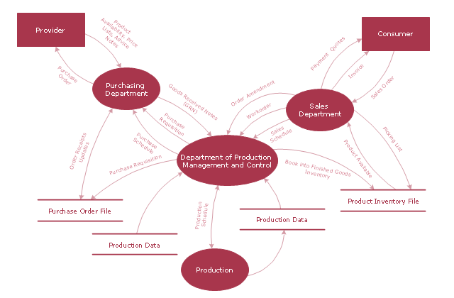
The DFD (Yourdon and Coad notation) example "Model of small traditional production enterprise" was created using the ConceptDraw PRO diagramming and vector drawing software extended with the Data Flow Diagrams solution from the Software Development area of ConceptDraw Solution Park.
It is common practice to draw a context-level Data flow diagram first which shows the interaction between the system and outside entities. The DFD is designed to show how a system is divided into smaller portions and to highlight the flow of data between those parts. This context-level Data flow diagram is then "exploded" to show more detail of the system being modeled" [Data model. Wikipedia]
The DFD (Yourdon and Coad notation) example "Model of small traditional production enterprise" was created using the ConceptDraw PRO diagramming and vector drawing software extended with the Data Flow Diagrams solution from the Software Development area of ConceptDraw Solution Park.
Data Flow Diagram Model
DFD Library — Design elements

Social Media Response DFD Flowcharts - diagramming software ( Mac PC )
 *")

Pyramid Diagram

Booch OOD Diagram

 Data Flow Diagrams (DFD)
Data Flow Diagrams solution extends ConceptDraw DIAGRAM software with templates, samples and libraries of vector stencils for drawing the data flow diagrams (DFD).
Database Flowchart Symbols

Pyramid Diagram

Components of ER Diagram

Functional Flow Block Diagram

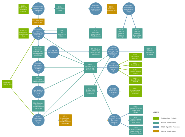
This DFD sample was created on the base of the figure from the NASA website. [asd-www.larc.nasa.gov/ ATBD/ DFD.html]
"Clouds and the Earth's Radiant Energy System (CERES).
EOS-Terra: Understanding Earth's Clouds and Climate.
The Clouds and the Earth's Radiant Energy System (CERES) instrument is one of several that will be flown aboard the Earth Observing System's Terra spacecraft, scheduled for launch in late1999. The data from the CERES instrument will be used to study the energy exchanged between the Sun; the Earth's atmosphere, surface and clouds; and outer space.
The CERES EOS-Terra instrument will be the second CERES instrument in Earth orbit. The first CERES instrument is currently orbiting the Earth aboard the Tropical Rainfall Measuring Mission observatory, which was launched in November 1997. Early results of the TRMM mission show that the first CERES has provided better measurement capabilities than any previous satellite instrument of its kind.
What CERES Will Measure.
CERES will measure the energy at the top of the atmosphere, as well as estimate energy levels in the atmosphere and at the Earth's surface. Using information from very high resolution cloud imaging instruments on the same spacecraft, CERES also will determine cloud properties, including cloud amount, altitude, thickness, and the size of the cloud particles. All of these measurements are critical for advancing our understanding of the Earth's total climate system and further improving climate prediction models.
The CERES instrument is based on NASA Langley's highly successful Earth Radiation Budget Experiment (ERBE) which used three satellites to provide global energy budget measurements from 1984 to 1990." [nasa.gov/ centers/ langley/ news/ factsheets/ CERES.html]
The DFD example "CERES data flow diagram" was created using the ConceptDraw PRO diagramming and vector drawing software extended with the Data Flow Diagrams solution from the Software Development area of ConceptDraw Solution Park.
DFD
ConceptDraw DIAGRAM DFD Software

Pyramid Diagram

Gane Sarson Diagram

Software Defined Networking System Overview


- Draw A Context Level Dfd 1st Level Dfd College Admission System
- First Level Dfd For College Management System
- Dfd For Admission System
- Draw A 0 Level And 1 Level Dfd Of A Online Admission System
- University System Dfd First Level
- Data Flow Diagrams | UML Use Case Diagram Example ...
- Data Flow Diagram For Student Admission System
- College Admissions Dfd 1st Level
- Data Flow Diagram For Admission System
- Dfd For Admission Management System
- Context Diagram Of Admission System
- Dfd Er Diagram Admissions System
- Dfd Context Level And First Level For College Management System
- Area Charts | Data Flow Diagram Of College Admission System
- 1st Level Of Library Management System Dfd
- Draw Data Flow Diagram For The Admission System
- UML Use Case Diagram Example. Registration System | Data Flow ...
- DFD - Model of small traditional production enterprise | Data Flow ...
- Process Flowchart | UML Use Case Diagram Example. Registration ...