The vector stencil library "HVAC ductwork" contains 63 duct and vent symbols.
Use it for drawing HVAC system diagrams, heating, ventilation, air conditioning, refrigeration, automated building control, and environmental control design floor
plans and equipment layouts.
"Ducts are used in heating, ventilation, and air conditioning (HVAC) to deliver and remove air. These needed airflows include, for example, supply air, return air, and exhaust air. Ducts also deliver, most commonly as part of the supply air, ventilation air. As such, air ducts are one method of ensuring acceptable indoor air quality as well as thermal comfort.
A duct system is often called ductwork. Planning ('laying out'), sizing, optimizing, detailing, and finding the pressure losses through a duct system is called duct design." [Duct (HVAC). Wikipedia]
The vector stencils example "Design elements - HVAC ductwork" is included in HVAC Plans solution from the Building Plans area of ConceptDraw Solution Park.
HVAC ductwork symbols

 HVAC Plans
Use HVAC Plans solution to create professional, clear and vivid HVAC-systems design plans, which represent effectively your HVAC marketing plan ideas, develop plans for modern ventilation units, central air heaters, to display the refrigeration systems for automated buildings control, environmental control, and energy systems.
The vector stencil library "HVAC equipment" contains 84 HVAC equipment symbols as pumps, fans, condensers, pipe coils, silencers, etc.
Use it for drawing HVAC system diagrams, heating, ventilation, air conditioning, refrigeration, automated building control, and environmental control design floor
plans and equipment layouts.
"HVAC (heating, ventilation, and air conditioning) is the technology of indoor and vehicular environmental comfort. HVAC system design is a subdiscipline of mechanical engineering, based on the principles of thermodynamics, fluid mechanics, and heat transfer. Refrigeration is sometimes added to the field's abbreviation as HVAC&R or HVACR, or ventilating is dropped as in HACR (such as the designation of HACR-rated circuit breakers).
HVAC is important in the design of medium to large industrial and office buildings such as skyscrapers and in marine environments such as aquariums, where safe and healthy building conditions are regulated with respect to temperature and humidity, using fresh air from outdoors." [HVAC. Wikipedia]
The vector stencils example "Design elements - HVAC equipment" is included in HVAC Plans solution from the Building Plans area of ConceptDraw Solution Park.
HVAC equipment symbols

The vector stencil library "HVAC control equipment" contains 81 HVAC control equipment icons.
Use it for drawing HVAC system diagrams, heating, ventilation, air conditioning, refrigeration, automated building control, and environmental control design floor
plans and equipment layouts.
"HVAC (stands for Heating, Ventilation and Air Conditioning) is a control system that applies regulation to a heating and/ or air conditioning system. Usually a sensing device is used to compare the actual state (e.g., temperature) with a target state. Then the control system draws a conclusion what action has to be taken (e.g., start the blower).
More complex HVAC systems can interface to Building Automation System (BAS) to allow the building owners to have more control over the heating or cooling units. The building owner can monitor the system and respond to alarms generated by the system from local or remote locations." [HVAC control system. Wikipedia]
The vector stencils example "Design elements - HVAC control equipment" is included in HVAC Plans solution from the Building Plans area of ConceptDraw Solution
Park.
HVAC control equipment symbols

Interior Design. Registers, Drills and Diffusers — Design Elements

The vector stencils library "HVAC ductwork" contains 55 duct and vent symbols of HVAC mechanical components. Use it for drawing HVAC ductwork system diagrams, heating, ventilation, air conditioning, refrigeration, automated building control, and environmental control design in the ConceptDraw PRO diagramming and vector drawing software extended with the HVAC Plans solution from the Building Plans area of ConceptDraw Solution Park.
Rect. duct, closed ends

Rect. duct, open 1 end

Rect. duct, open both ends

Circ. duct, closed ends

Circ. duct, open 1 end

Circ. duct, open both ends

Branch duct, rectangular

Branch duct, circular

Variable bend

Miter bend

Y junction

3 way junction

Junction 1

Beveled junction, rect. duct, rect. branch

Beveled junction, rect. duct, circ. branch

Beveled junction, circ. duct, rect. branch

Beveled junction, circ. duct, circ. branch

Transition, rect. to rect.

Transition, rect. to circ.

Transition, circ. to rect.

Transition, circ. to circ.

Offset transition, rect. to rect.

Offset transition, rect. to circ.

Offset transition, circ. to rect.

Offset transition, circ. to circ.

Flexible connection, rect. duct

Flexible connection, circ. duct

Flexible connection 2, rect. duct

Flexible connection 2, circ. duct

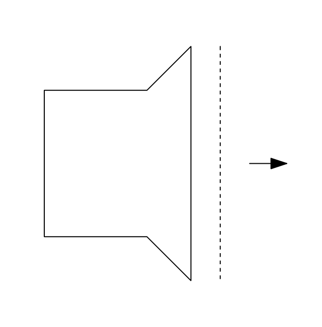
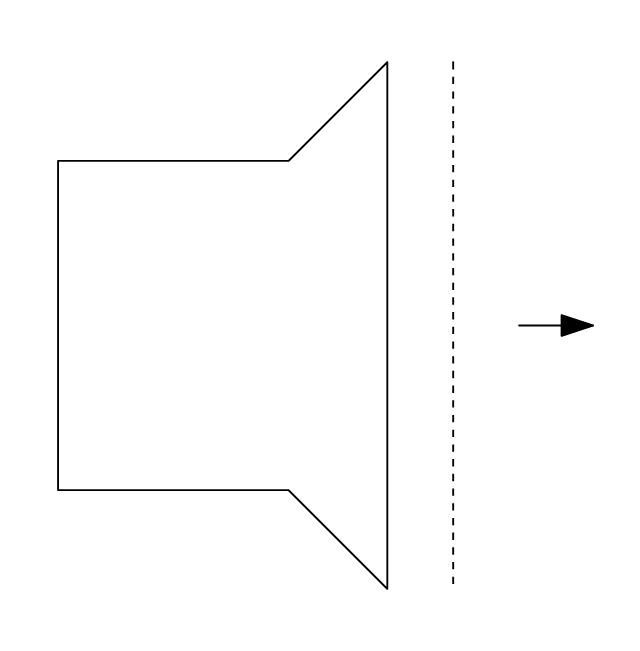
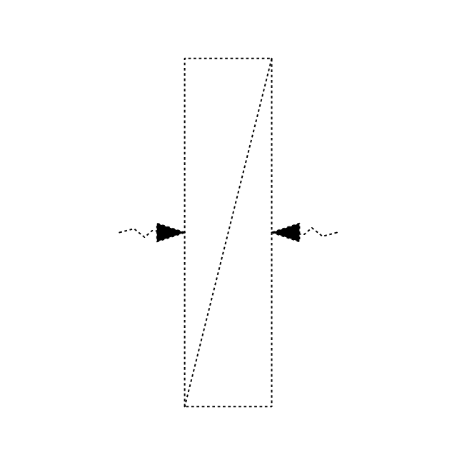
Supply, rect. duct toward

Supply, rect. duct away

Supply, rect. duct, elbow away

Supply, circ. duct toward

Supply, circ. duct away

Supply, circ. duct, elbow away

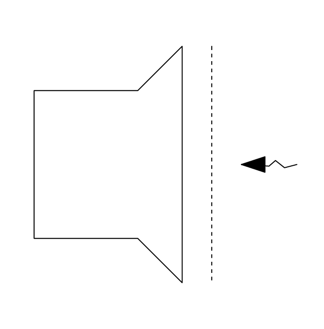
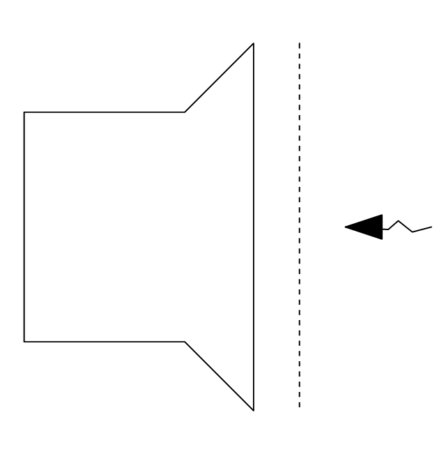
Return, rect. duct toward

Return, rect. duct away

Return, rect. duct, elbow away

Return, circ. duct toward

Return, circ. duct away

Return, circ. duct, elbow away

Sliding damper, rect. duct

Sliding damper, circ. duct

Damper, ACD

Damper, BD

Damper, FD/AD

Damper, MD

Damper, SD/AD

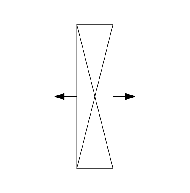
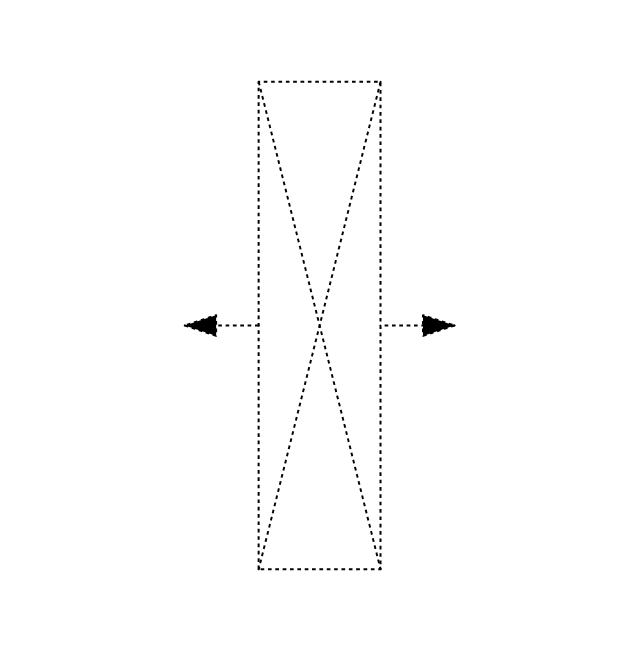
Vert. duct, rect. duct toward

Vert. duct, rect. duct away

Vert. duct, rect. duct, elbow away

Vert. duct, circ. duct toward

Vert. duct, circ. duct away

Vert. duct, circ. duct, elbow away

VAV box

The vector stencils library Registers, drills and diffusers contains 47 symbols of rectangular, circular, linear and troffer air handling inlet/ outlet components.
Use the design elements library Registers, drills and diffusers to draw reflected ceiling plans (RCP) and HVAC layout floor plans using the ConceptDraw PRO diagramming and vector drawing software.
"A ceiling is an overhead interior surface that covers the upper limit of a room. It is not generally considered a structural element, but a finished surface concealing the underside of the floor or roof structure above.
Ceilings are classified according to their appearance or construction. A cathedral ceiling is any tall ceiling area similar to those in a church. A dropped ceiling is one in which the finished surface is constructed anywhere from a few inches to several feet below the structure above it. This may be done for aesthetic purposes, such as achieving a desirable ceiling height; or practical purposes such as providing a space for HVAC or piping. An inverse of this would be a raised floor. A concave or barrel shaped ceiling is curved or rounded, usually for visual or acoustical value, while a coffered ceiling is divided into a grid of recessed square or octagonal panels, also called a "lacunar ceiling". A cove ceiling uses a curved plaster transition between wall and ceiling; it is named for cove molding, a molding with a concave curve." [Ceiling. Wikipedia]
"... reflected Ceiling Plans (RCP)s showing ceiling layouts appear after the floor plans." [Plan (drawing). Wikipedia]
The shapes library "Registers, drills and diffusers" is contained in the Reflected Ceiling Plans solution from the Building Plans area of ConceptDraw Solution Park.
Reflected ceiling plan symbols

Building Drawing. Design Element: Piping Plan


HelpDesk
How to Create a HVAC Plan

 Reflected Ceiling Plans
Reflected Ceiling Plans solution extends greatly the ConceptDraw DIAGRAM functionality with samples, templates and libraries of design elements for displaying the ceiling ideas for living room, bedroom, classroom, office, shop, restaurant, and many other premises. It is an effective tool for architects, designers, builders, electricians, and other building-related people to represent their ceiling design ideas and create Reflected Ceiling plan or Reflective Ceiling plan, showing the location of light fixtures, lighting panels, drywall or t-bar ceiling patterns, HVAC grilles or diffusers that may be suspended from the ceiling. Being professional-looking and vivid, these plans perfectly reflect your ceiling ideas and can be presented to the client, in reports, in presentations, on discussions with colleagues, or successfully published in modern print or web editions.
Classroom Seating Chart Maker

HVAC Business Plan

This mechanical room HVAC plan sample shows the layout of air handler (air handling unit, AHU) equipment: mixing chamber, air filter, fan (blower), heat exchanger coil, diffusers.
"Ventilating (the V in HVAC) is the process of "changing" or replacing air in any space to provide high indoor air quality (i.e. to control temperature, replenish oxygen, or remove moisture, odors, smoke, heat, dust, airborne bacteria, and carbon dioxide). Ventilation is used to remove unpleasant smells and excessive moisture, introduce outside air, to keep interior building air circulating, and to prevent stagnation of the interior air.
Ventilation includes both the exchange of air to the outside as well as circulation of air within the building. It is one of the most important factors for maintaining acceptable indoor air quality in buildings. Methods for ventilating a building may be divided into mechanical/ forced and natural types.
"Mechanical" or "forced" ventilation is used to control indoor air quality. Excess humidity, odors, and contaminants can often be controlled via dilution or replacement with outside air. However, in humid climates much energy is required to remove excess moisture from ventilation air.
Ventilation increases the energy needed for heating or cooling, however heat recovery ventilation can be used to mitigate the energy consumption. This involves heat exchange between incoming and outgoing air. Energy recovery ventilation additionally includes exchange of humidity." [Ventilation (architecture). Wikipedia]
The HVAC floor plan example "Ventilation system layout" was created using the ConceptDraw DIAGRAM diagramming and vector drawing software extended with the HVAC Plans solution from the Building Plans area of ConceptDraw Solution Park.
HVAC floor plan

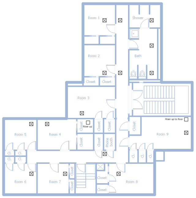
This school HVAC plan sample represent layout of air conditioning ductwork inlets and outlets.
"Air conditioning (often referred to as A/ C or AC) is the process of altering the properties of air (primarily temperature and humidity) to more comfortable conditions, typically with the aim of distributing the conditioned air to an occupied space such as a building or a vehicle to improve thermal comfort and indoor air quality. In common use, an air conditioner is a device that removes heat from the air inside a building or vehicle, thus lowering the air temperature. The cooling is typically achieved through a refrigeration cycle, but sometimes evaporation or free cooling is used. Air conditioning systems can also be made based on desiccants." [Air conditioning. Wikipedia]
The fllor plan example "School HVAC plan" was created using the ConceptDraw DIAGRAM diagramming and vector drawing software extended with the HVAC Plans solution from the Building Plans area of ConceptDraw Solution Park.
Floor plan
The vector stencils library Registers, drills and diffusers contains 47 symbols of rectangular, circular, linear and troffer air handling inlet/ outlet components.
Use the design elements library Registers, drills and diffusers to draw reflected ceiling plans (RCP) and HVAC layout floor plans using the ConceptDraw PRO diagramming and vector drawing software.
"A ceiling is an overhead interior surface that covers the upper limit of a room. It is not generally considered a structural element, but a finished surface concealing the underside of the floor or roof structure above.
Ceilings are classified according to their appearance or construction. A cathedral ceiling is any tall ceiling area similar to those in a church. A dropped ceiling is one in which the finished surface is constructed anywhere from a few inches to several feet below the structure above it. This may be done for aesthetic purposes, such as achieving a desirable ceiling height; or practical purposes such as providing a space for HVAC or piping. An inverse of this would be a raised floor. A concave or barrel shaped ceiling is curved or rounded, usually for visual or acoustical value, while a coffered ceiling is divided into a grid of recessed square or octagonal panels, also called a "lacunar ceiling". A cove ceiling uses a curved plaster transition between wall and ceiling; it is named for cove molding, a molding with a concave curve." [Ceiling. Wikipedia]
"... reflected Ceiling Plans (RCP)s showing ceiling layouts appear after the floor plans." [Plan (drawing). Wikipedia]
The shapes library "Registers, drills and diffusers" is contained in the Reflected Ceiling Plans solution from the Building Plans area of ConceptDraw Solution Park.
Use the design elements library Registers, drills and diffusers to draw reflected ceiling plans (RCP) and HVAC layout floor plans using the ConceptDraw PRO diagramming and vector drawing software.
"A ceiling is an overhead interior surface that covers the upper limit of a room. It is not generally considered a structural element, but a finished surface concealing the underside of the floor or roof structure above.
Ceilings are classified according to their appearance or construction. A cathedral ceiling is any tall ceiling area similar to those in a church. A dropped ceiling is one in which the finished surface is constructed anywhere from a few inches to several feet below the structure above it. This may be done for aesthetic purposes, such as achieving a desirable ceiling height; or practical purposes such as providing a space for HVAC or piping. An inverse of this would be a raised floor. A concave or barrel shaped ceiling is curved or rounded, usually for visual or acoustical value, while a coffered ceiling is divided into a grid of recessed square or octagonal panels, also called a "lacunar ceiling". A cove ceiling uses a curved plaster transition between wall and ceiling; it is named for cove molding, a molding with a concave curve." [Ceiling. Wikipedia]
"... reflected Ceiling Plans (RCP)s showing ceiling layouts appear after the floor plans." [Plan (drawing). Wikipedia]
The shapes library "Registers, drills and diffusers" is contained in the Reflected Ceiling Plans solution from the Building Plans area of ConceptDraw Solution Park.
Reflected ceiling plan symbols
CCTV Network Diagram Software

Interior Design

 Plumbing and Piping Plans
Plumbing and Piping Plans solution extends ConceptDraw DIAGRAM software with samples, templates and libraries of pipes, plumbing, and valves design elements for developing of water and plumbing systems, and for drawing Plumbing plan, Piping plan, PVC Pipe plan, PVC Pipe furniture plan, Plumbing layout plan, Plumbing floor plan, Half pipe plans, Pipe bender plans.
The vector stencils library "Registers, drills and diffusers" contains 47 shapes of rectangular, circular, linear and troffer air handling inlet/ outlet components, registers, drills and diffusers. Use it for drawing reflected ceiling plans and HVAC plans in the ConceptDraw PRO diagramming and vector drawing software extended with the Reflected Ceiling Plans solution from the Building Plans area of ConceptDraw Solution Park.
Rectangular inlet
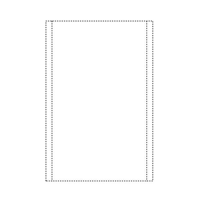
Rectangular inlet, hidden
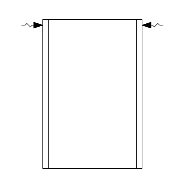
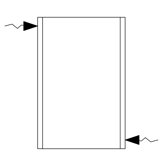
Rectangular inlet, flow arrow
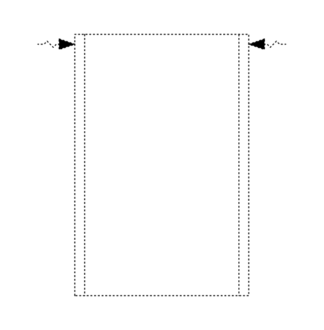
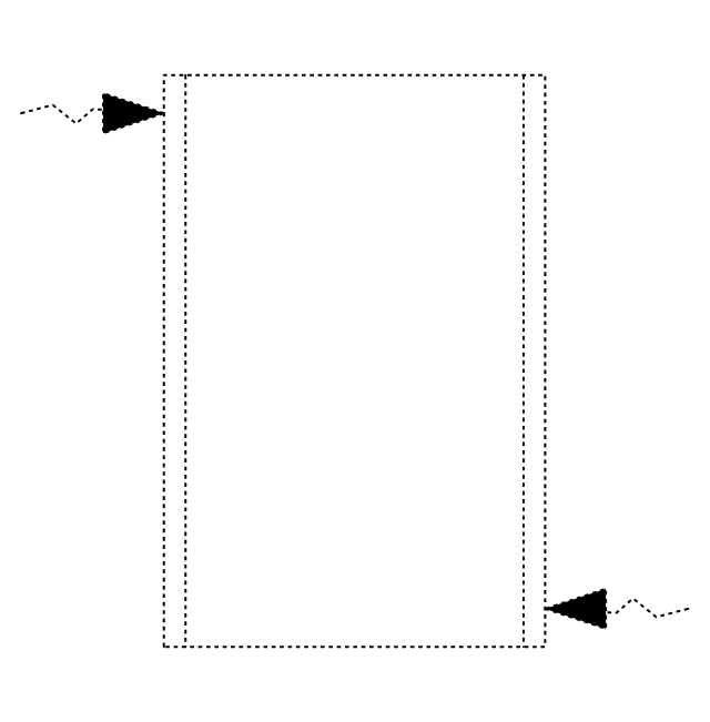
Rectangular inlet, flow arrow, hidden
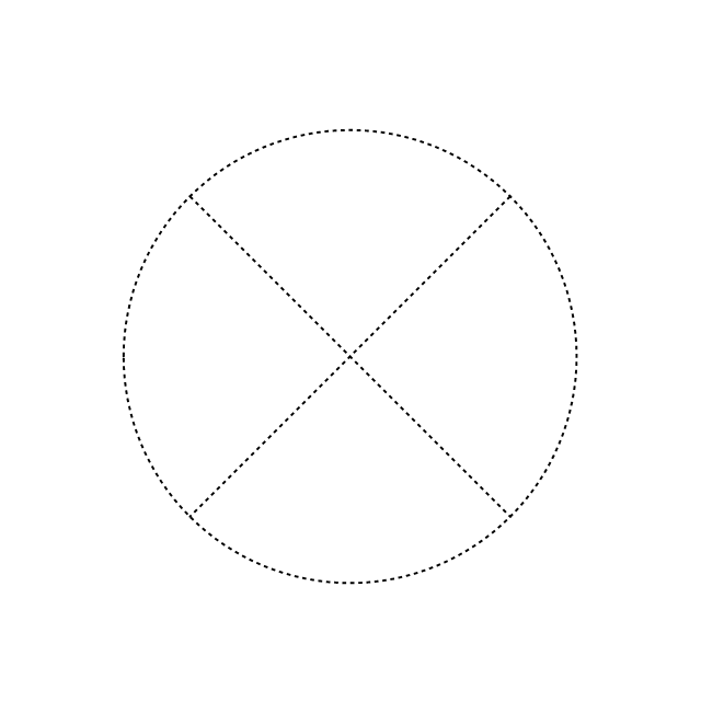
Circular inlet
Circular inlet, hidden
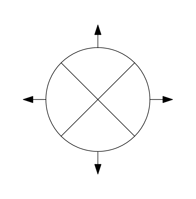
Circular inlet, flow arrow
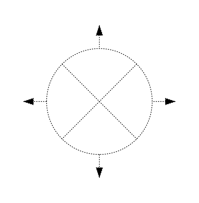
Circular inlet, flow arrow, hidden
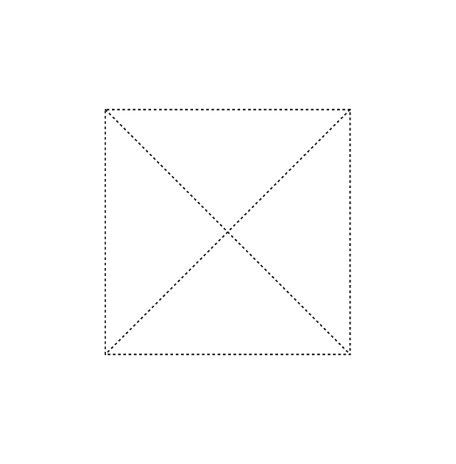
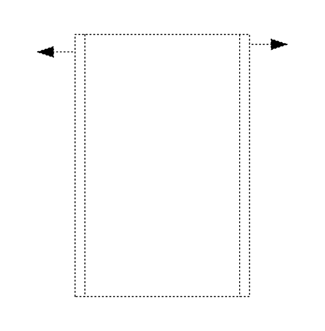
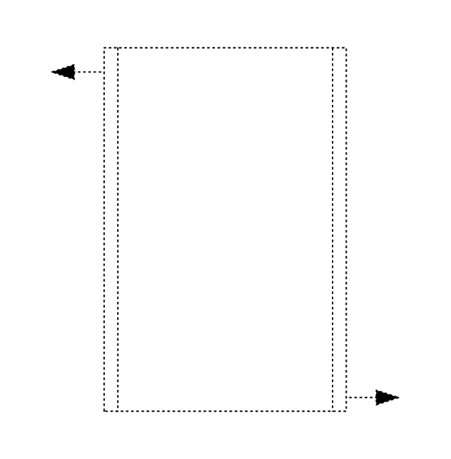
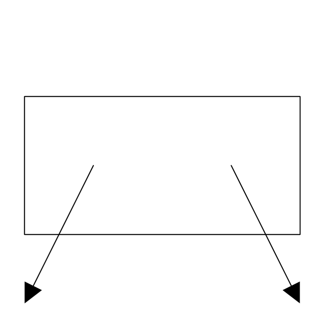
Rectangular outlet
Rectangular outlet, hidden
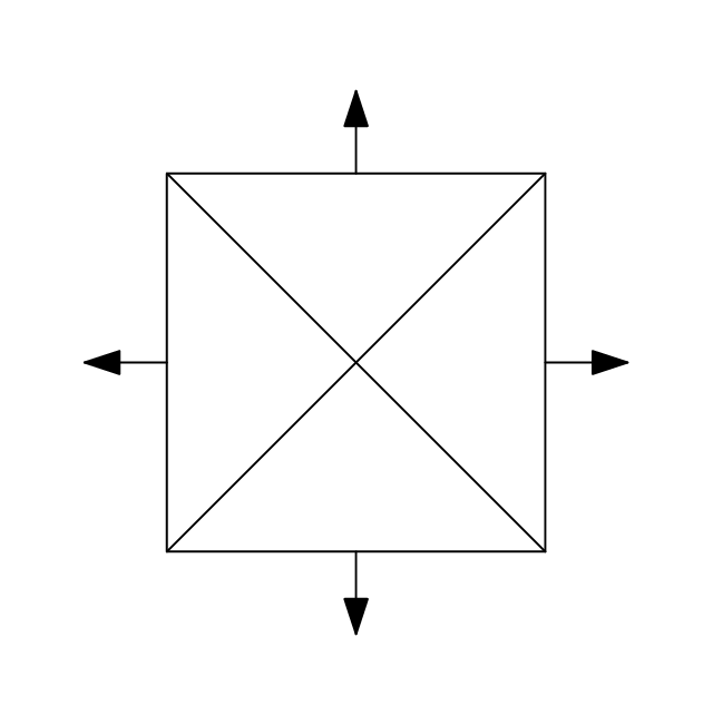
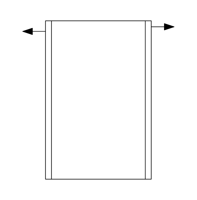
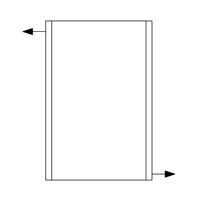
Rectangular outlet, flow arrows
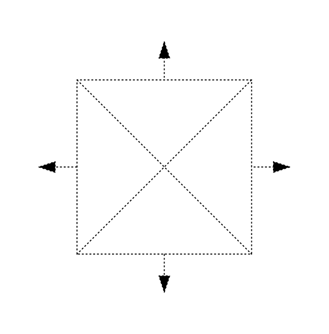
Rectangular outlet, flow arrows, hidden
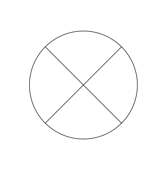
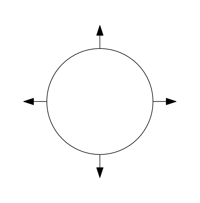
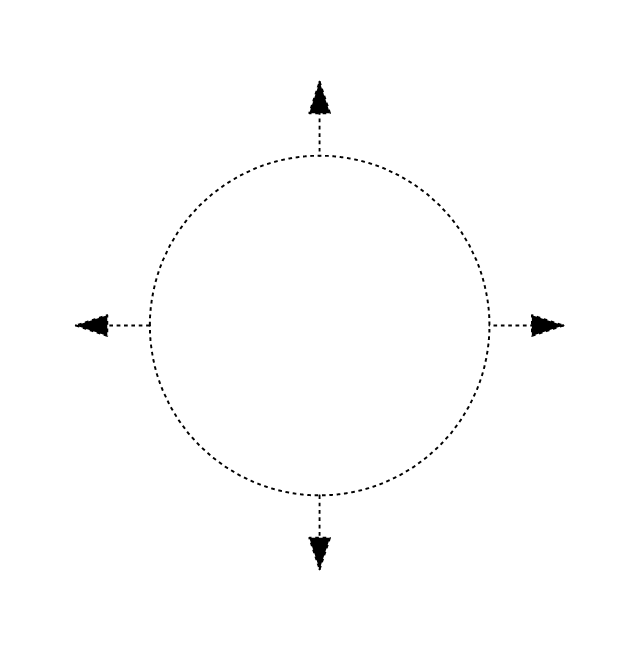
Circular outlet
Circular outlet, hidden
Circular outlet, flow arrows
Circular outlet, flow arrows, hidden
Grille diffuser, rectangular duct
Grille diffuser, circular duct

Return grille diffuser, rectangular duct
Return grille diffuser, circular duct
Supply grille diffuser, rectangular duct
Supply grille diffuser, circular duct
Linear return diffuser
Linear return diffuser, hidden
Linear supply diffuser

Linear supply diffuser, hidden
Linear return diffuser, flow arrows
Linear return diffuser, flow arrows, hidden
Linear supply diffuser, flow arrows
Linear supply diffuser, flow arrows, hidden
Troffer inlet / outlet
Troffer inlet / outlet, hidden
Troffer inlet, return diffuser
Troffer inlet, return diffuser, hidden
Troffer inlet, supply diffuser
Troffer inlet, supply diffuser, hidden
Troffer outlet, return diffuser
Troffer outlet, return diffuser, hidden
Troffer outlet, supply diffuser
Troffer outlet, supply diffuser, hidden
Circular outlet
Circular outlet, hidden
Grille
Grille, hidden
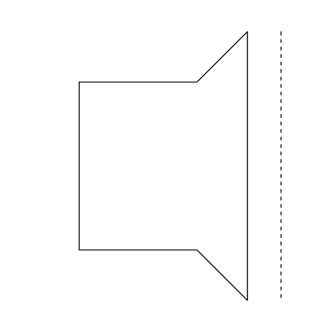
Grille (side)
-registers,-drills-and-diffusers---vector-stencils-library.png--diagram-flowchart-example.png)
Grille (side), return diffuser
,-return-diffuser-registers,-drills-and-diffusers---vector-stencils-library.png--diagram-flowchart-example.png)
Grille (side), supply diffuser
,-supply-diffuser-registers,-drills-and-diffusers---vector-stencils-library.png--diagram-flowchart-example.png)
- Ductwork layout | HVAC Plans | Design elements - HVAC ductwork ...
- Design elements - HVAC ductwork | Duct Sign In Drawing
- Design elements - HVAC ductwork | Ductwork layout | Interior ...
- Design elements - HVAC ductwork | Interior Design . Registers, Drills ...
- Design elements - HVAC ductwork | HVAC ductwork - Vector ...
- Design elements - HVAC ductwork | Ductwork layout | Building ...
- Ductwork layout | Design elements - HVAC ductwork | HVAC control ...
- Interior Design . Registers, Drills and Diffusers — Design Elements ...
- Design elements - HVAC ductwork | HVAC Business Plan | HVAC ...