UML Deployment Diagram. Design Elements

ConceptDraw has 393 vector stencils in the 13 libraries that helps you to start using software for designing your own UML Diagrams. You can use the appropriate stencils of UML notation from UML Deployment library.
UML Deployment Diagram. Diagramming Software for Design UML Diagrams


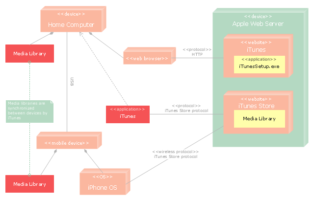
"iTunes is a media player, media library, and mobile device management application developed by Apple Inc. It is used to play, download, and organize digital audio and video on personal computers running the OS X and Microsoft Windows operating systems. The iTunes Store is also available on the iPod Touch, iPhone, and iPad.
Through the iTunes Store, users can purchase and download music, music videos, television shows, audiobooks, podcasts, movies, and movie rentals in some countries, and ringtones, available on the iPhone and iPod Touch (fourth generation onward). Application software for the iPhone, iPad and iPod Touch can be downloaded from the App Store." [iTunes. Wikipedia]
The UML deployment diagram example "Apple iTunes" was created using the ConceptDraw PRO diagramming and vector drawing software extended with the Rapid UML solution from the Software Development area of ConceptDraw Solution Park.
UML deployment diagram
UML Deployment Diagram

Use ConceptDraw DIAGRAM with UML deployment diagram templates, samples and stencil library from Rapid UML solution to model the physical deployment of artifacts on nodes of your software system.
UML Deployment Diagram Example - ATM System UML diagrams

This sample shows the work of the ATM (Automated Teller Machine) banking system that is used for service and performing of the banking transactions using ATMs. System engineers can use comprehensive UML diagrams solution.
UML Component Diagram

UML Component Diagram Example - Online Shopping

This sample shows the concept of the online shopping and is used for the understanding of the online shopping processes, of the online shops working processes, for projection and creating of the online stores.
Banking System

UML Use Case Diagram Example - Estate Agency

This sample shows the work of the estate agency and is used by the estate agencies, building companies, at the trainings of the estate agencies, for understanding the working processes of the estate agencies.
The vector stencils library "Bank UML deployment diagram" contains 10 shapes for drawing UML deployment diagrams.
Use it for object-oriented modeling of your bank information system.
"A deployment diagram in the Unified Modeling Language models the physical deployment of artifacts on nodes. To describe a web site, for example, a deployment diagram would show what hardware components ("nodes") exist (e.g., a web server, an application server, and a database server), what software components ("artifacts") run on each node (e.g., web application, database), and how the different pieces are connected (e.g. JDBC, REST, RMI).
The nodes appear as boxes, and the artifacts allocated to each node appear as rectangles within the boxes. Nodes may have subnodes, which appear as nested boxes. A single node in a deployment diagram may conceptually represent multiple physical nodes, such as a cluster of database servers.
There are two types of Nodes:
1. Device Node.
2. Execution Environment Node.
Device nodes are physical computing resources with processing memory and services to execute software, such as typical computers or mobile phones. An execution environment node (EEN) is a software computing resource that runs within an outer node and which itself provides a service to host and execute other executable software elements." [Deployment diagram. Wikipedia]
This example of UML deployment diagram symbols for the ConceptDraw PRO diagramming and vector drawing software is included in the ATM UML Diagrams solution from the Software Development area of ConceptDraw Solution Park.
UML deployment diagram symbols

UML Diagram Types List

Basic Audit Flowchart. Flowchart Examples

The Audit Flowcharts are widely used in the financial management, accounting, money management and in many others fields.
Online Diagram Tool

UML Class Diagram Example - Medical Shop

This sample shows the work of the medical shop and is used at the creation of the medical shop or pharmacy project, for understanding the process of shopping in the medical shop, for keeping purchases, for medical supplies.
UML Class Diagram Constructor

The Rapid UML Solution for ConceptDraw DIAGRAM includes the UML Class Diagram library that helps you to design the UML Class Diagram quick and easy. You can simply and quickly drop the ready-to-use objects from the library into your document to create the UML Class Diagram.
 ATM UML Diagrams
The ATM UML Diagrams solution lets you create ATM solutions and UML examples. Use ConceptDraw DIAGRAM as a UML diagram creator to visualize a banking system.
UML Use Case Diagram Example. Services UML Diagram. ATM system

This sample shows the scheme of the servicing using the ATMs (Automated Teller Machines) and is used at the working of ATM banking systems, at the performing of the banking transactions.
About UML

This sample shows the work of the taxi service and is used by taxi stations, by airports, in the tourism field and delivery service.
UML Class Diagram Example for GoodsTransportation System

This sample shows the concept of working of the transport company and is used by transport companies, carriers at the transportation of various goods.
UML Collaboration Diagram Example Illustration

This sample shows the creation process of the contact list and can be used at the staff training and staff working, at the attraction process the new clients.
- Interaction Overview Diagram | UML Deployment Diagram Example ...
- Deployment Diagram Of Library Management System
- Draw Component Diagram For Library Management System And
- Component Diagram For Library Management System In Uml
- Interaction Overview Diagram | UML Component Diagram Example ...
- Component Diagram For Library Management System Pdf
- UML Deployment Diagram Example - ATM System UML diagrams ...
- Venn Diagrams | Draw A Component Diagram For Library System
- Component Diagram For Library Management System
- Deployement For Library Management System Uml Diagram Pdf
- Draw A Component Diagram For Library Information System
- DFD Library System | UML Package Diagram . Design Elements ...
- UML Component Diagram . Design Elements | UML Deployment ...
- Component Diagram For Library Management
- UML Deployment Diagram Example - ATM System UML diagrams ...
- UML Activity Diagram | Diagramming Software for Design UML ...
- Object Diagram For Library Management System Ppt
- UML Component Diagram . Design Elements | Flowcharts | Local ...
- Draw A Object Diagram For Library Management System
- Deployment Diagram Of Library Management Diagram Images
- ERD | Entity Relationship Diagrams, ERD Software for Mac and Win
- Flowchart | Basic Flowchart Symbols and Meaning
- Flowchart | Flowchart Design - Symbols, Shapes, Stencils and Icons
- Flowchart | Flow Chart Symbols
- Electrical | Electrical Drawing - Wiring and Circuits Schematics
- Flowchart | Common Flowchart Symbols
- Flowchart | Common Flowchart Symbols