Diagramming Software for Design UML Collaboration Diagrams


Diagramming Software for Design UML Object Diagrams

UML Collaboration Diagram Example Illustration

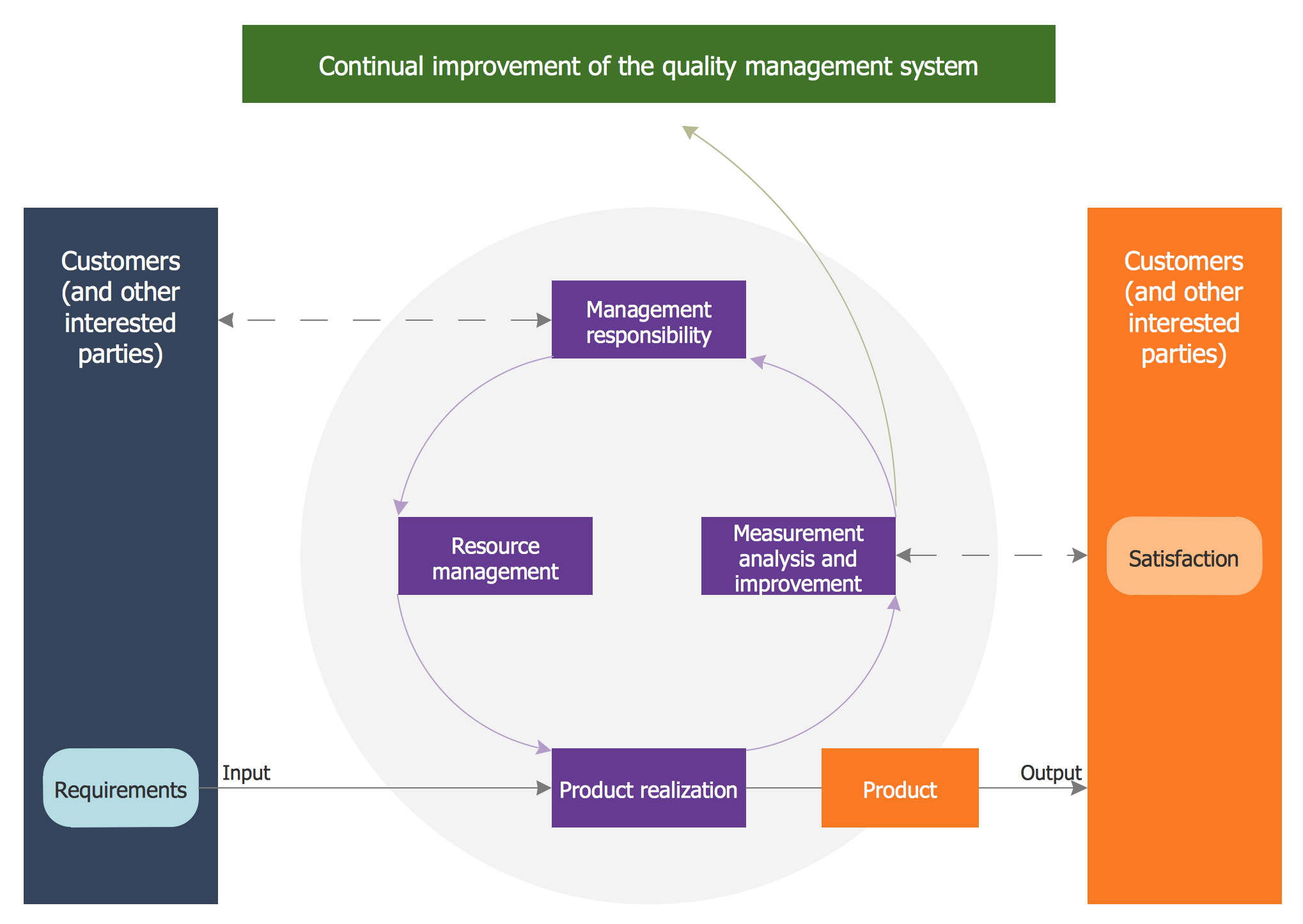
Quality Management System
UML Diagrams with ConceptDraw DIAGRAM

UML Collaboration Diagram (UML2.0)

UML Deployment Diagram Example - ATM System UML diagrams

 AWS Architecture Diagrams
AWS Architecture Diagrams with powerful drawing tools and numerous predesigned Amazon icons and AWS simple icons is the best for creation the AWS Architecture Diagrams, describing the use of Amazon Web Services or Amazon Cloud Services, their application for development and implementation the systems running on the AWS infrastructure. The multifarious samples give you the good understanding of AWS platform, its structure, services, resources and features, wide opportunities, advantages and benefits from their use; solution’s templates are essential and helpful when designing, description and implementing the AWS infrastructure-based systems. Use them in technical documentation, advertising and marketing materials, in specifications, presentation slides, whitepapers, datasheets, posters, etc.
Diagramming Software for Design UML Component Diagrams

UML Package Diagram. Design Elements

 Fishbone Diagram
Fishbone Diagrams solution extends ConceptDraw DIAGRAM software with templates, samples and library of vector stencils for drawing the Ishikawa diagrams for cause and effect analysis.
DFD Library System

UML Business Process

 Enterprise Architecture Diagrams
Enterprise Architecture Diagrams solution extends ConceptDraw DIAGRAM software with templates, samples and library of vector stencils for drawing the diagrams of enterprise architecture models.
 Event-driven Process Chain Diagrams
Event-Driven Process Chain Diagrams solution extends ConceptDraw DIAGRAM functionality with event driven process chain templates, samples of EPC engineering and modeling the business processes, and a vector shape library for drawing the EPC diagrams and EPC flowcharts of any complexity. It is one of EPC IT solutions that assist the marketing experts, business specialists, engineers, educators and researchers in resources planning and improving the business processes using the EPC flowchart or EPC diagram. Use the EPC solutions tools to construct the chain of events and functions, to illustrate the structure of a business process control flow, to describe people and tasks for execution the business processes, to identify the inefficient businesses processes and measures required to make them efficient.
- Sample Object Diagram For Library Management System
- Example Component Diagrams For Library Management System
- Component Diagram For Library Management System In Uml
- Sequence Diagram For Library Management System Ppt
- Object Diagram For Library Management System Ppt
- Composite Diagram For Library Management System
- Package Diagram For Library System
- Did Diagram Library Management System
- Deployment Diagram For Library Management System Pdf
- Draw Component Diagram For Library Management System And
- All Uml Diagrams For Library Management System Pdf
- Symbols Used In Deployment Diagram For Library Management
- Object Diagram For Library Management System Pdf
- Component Diagram Of Library Management System
- Use Case Diagram For Library Management System Ppt Download
- Collaboration Diagram For Library Management System Project
- Use Case Diagram For Library Management System Visio
- Activity Diagram For Library Management System In Uml
- UML Sequence Diagram Example. SVG Vectored UML Diagrams ...
- Package Diagram For Library Management System Pdf