Metropolitan area networks (MAN). Computer and Network Examples
. Computer and Network Examples")

Local area network (LAN). Computer and Network Examples
 diagram")
Personal area (PAN) networks. Computer and Network Examples
 networks")
Campus Area Networks (CAN). Computer and Network Examples
. <br>Computer and Network Examples *")
Network Topologies


Hybrid Network Topology

WLAN

Entity Relationship Diagram Symbols

Computer Network. Computer and Network Examples


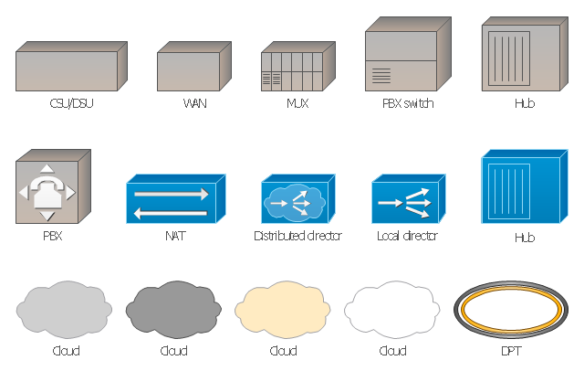
The vector stencils library "Cisco WAN" contains 15 symbols of wide area network (WAN) devices and equipment for drawing Cisco WAN diagrams.
"A wide area network (WAN) is a network that covers a broad area (i.e., any telecommunications network that links across metropolitan, regional, or national boundaries) using leased telecommunication lines. Business and government entities utilize WANs to relay data among employees, clients, buyers, and suppliers from various geographical locations. ...
Related terms for other types of networks are personal area networks (PANs), local area networks (LANs), campus area networks (CANs), or metropolitan area networks (MANs) which are usually limited to a room, building, campus or specific metropolitan area (e.g., a city) respectively.
... it may be best to view WANs as computer networking technologies used to transmit data over long distances, and between different LANs, MANs and other localised computer networking architectures. ...
WANs are often built using leased lines. At each end of the leased line, a router connects the LAN on one side with a second router within the LAN on the other. Leased lines can be very expensive. Instead of using leased lines, WANs can also be built using less costly circuit switching or packet switching methods. Network protocols including TCP/ IP deliver transport and addressing functions. Protocols including Packet over SONET/ SDH, MPLS, ATM and Frame relay are often used by service providers to deliver the links that are used in WANs." [Wide area network. Wikipedia]
The symbols example "Cisco WAN - Vector stencils library" was created using the ConceptDraw PRO diagramming and vector drawing software extended with the Cisco Network Diagrams solution from the Computer and Networks area of ConceptDraw Solution Park.
www.conceptdraw.com/ solution-park/ computer-networks-cisco
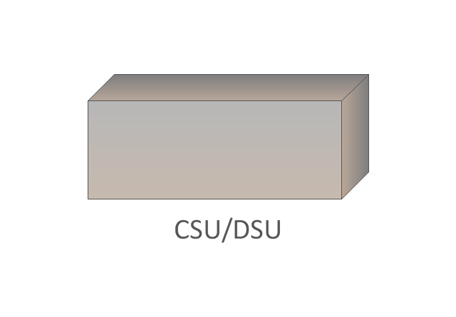
CSU/DSU
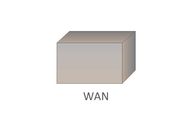
WAN
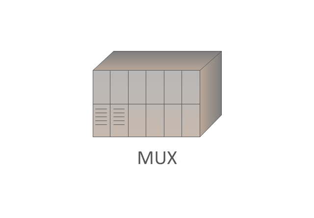
MUX
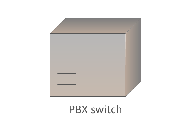
PBX switch
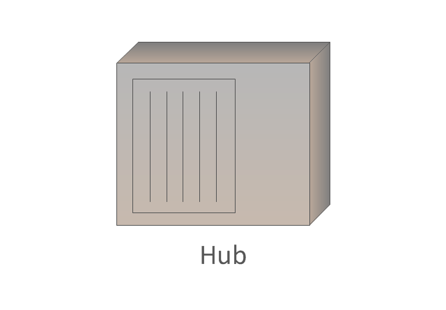
Hub
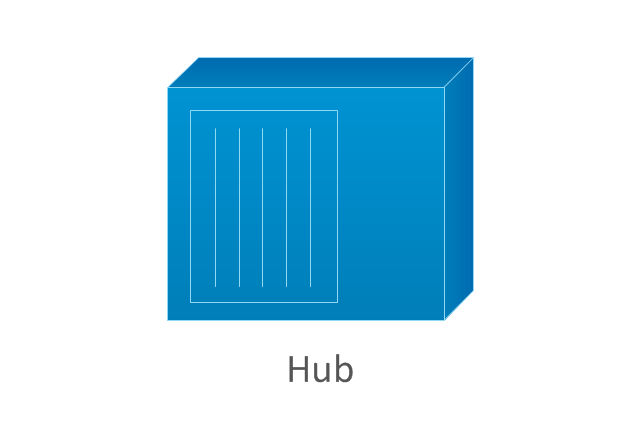
Hub, blue
NAT

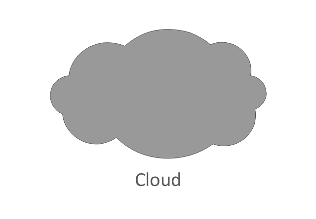
Network cloud, dark
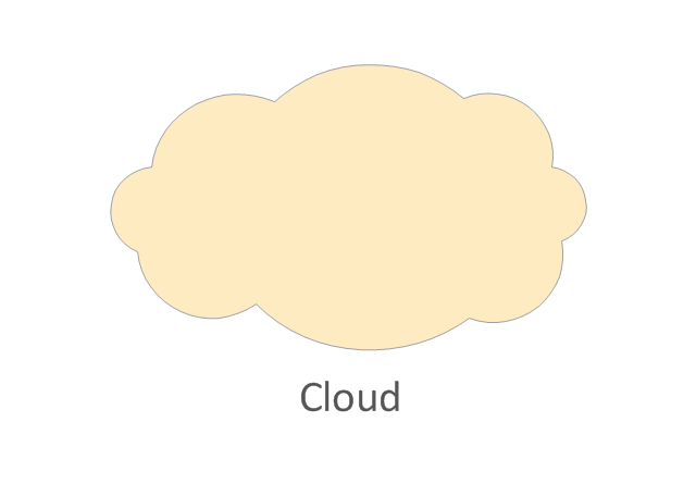
Network cloud, gold
Network cloud, white
Network cloud, standard color
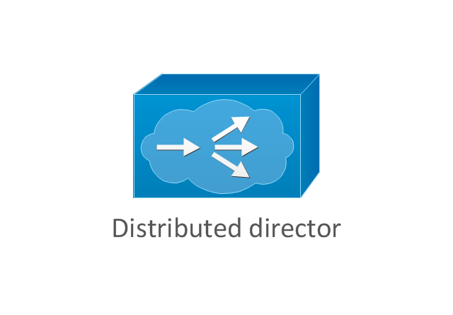
Distributed director
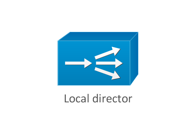
Local director
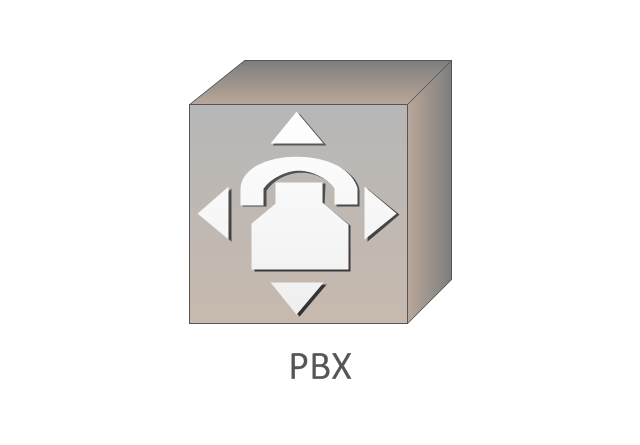
PBX
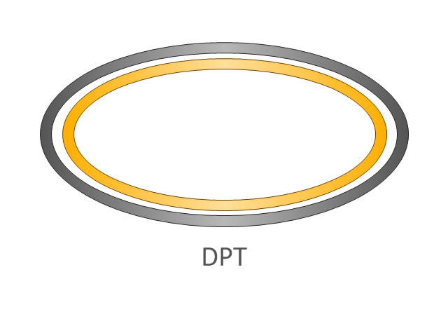
DPT
Cloud Computing Architecture Diagrams

The vector stencils library "Cisco LAN" contains 23 symbols of local area network (LAN) devices and equipment for drawing Cisco LAN topology diagrams.
"Network topology describes the layout of interconnections between devices and network segments. At the Data Link Layer and Physical Layer, a wide variety of LAN topologies have been used, including ring, bus, mesh and star, but the most common LAN topology in use today is switched Ethernet. At the higher layers, the Internet Protocol (TCP/ IP) has become the standard, replacing NetBEUI, IPX/ SPX, AppleTalk and others.
Simple LANs generally consist of one or more switches. A switch can be connected to a router, cable modem, or ADSL modem for Internet access. Complex LANs are characterized by their use of redundant links with switches using the spanning tree protocol to prevent loops, their ability to manage differing traffic types via quality of service (QoS), and to segregate traffic with VLANs. A LAN can include a wide variety of network devices such as switches, firewalls, routers, load balancers, and sensors.
LANs can maintain connections with other LANs via leased lines, leased services, or the Internet using virtual private network technologies. Depending on how the connections are established and secured in a LAN, and the distance involved, a LAN may also be classified as a metropolitan area network (MAN) or a wide area network (WAN)." [Local area network. Wikipedia]
The symbols example "Cisco LAN - Vector stencils library" was created using the ConceptDraw PRO diagramming and vector drawing software extended with the Cisco Network Diagrams solution from the Computer and Networks area of ConceptDraw Solution Park.
www.conceptdraw.com/ solution-park/ computer-networks-cisco
Sun workstation

Workstation

PC

Macintosh

Terminal

Mini VAX

Printer

Laptop

File server

Monitor

Web cluster

ATM fast gigabit etherswitch

HP Mini

Supercomputer

LAN2LAN

LAN to LAN

Web server

Web browser

Repeater

PDA

General appliance

PC, blue

Mini VAX, blue

ATM Network. Computer and Network Examples

ConceptDraw Arrows10 Technology

The vector stencils library "Cisco WAN" contains 15 symbols of wide area network (WAN) devices and equipment: CSU/ DSU (Channel Service Unit/ Data Service Unit), WAN, MUX (multiplexer), PBX switch, Hub, NAT (network address translation), distributed and local directors, PBX (private branch exchange), Network clouds, DPT (dynamic packet transport).
Create the computer network topology diagrams using the ConceptDraw PRO diagramming and vector drawing software with the design elements library "Cisco WAN".
"A wide area network (WAN) is a network that covers a broad area (i.e., any telecommunications network that links across metropolitan, regional, or national boundaries) using private or public network transports. Business and government entities utilize WANs to relay data among employees, clients, buyers, and suppliers from various geographical locations. In essence, this mode of telecommunication allows a business to effectively carry out its daily function regardless of location. The Internet can be considered a WAN as well, and is used by businesses, governments, organizations, and individuals for almost any purpose imaginable.
Related terms for other types of networks are personal area networks (PANs), local area networks (LANs), campus area networks (CANs), or metropolitan area networks (MANs) which are usually limited to a room, building, campus or specific metropolitan area (e.g., a city) respectively." [Wide area network. Wikipedia]
The example "Design elements - Cisco WAN" is included in the Cisco Network Diagrams solution from the Computer and Networks area of ConceptDraw Solution Park.
Cisco WAN symbols
How to Draw a Computer Network Diagrams

UML Composite Structure Diagram


Example of DFD for Online Store (Data Flow Diagram)


Value stream with ConceptDraw DIAGRAM

- Metropolitan area networks (MAN). Computer and Network Examples
- Explain Metropolitan Area Network In Detail With Diagram
- With Aid Of Diagram Describe A Metropolitan Area Network
- A Diagram To Describe A Metropolitan Area Network
- Metropolitan area networks (MAN). Computer and Network ...
- Metropolitan area networks (MAN). Computer and Network Examples
- Explain Metropolitan Area Network With Diagram
- Metropolitan area networks (MAN). Computer and Network Examples
- Metro Map | Explain The Metropolitan Area Network With Diagram
- Local area network (LAN). Computer and Network Examples ...
- Local area network (LAN). Computer and Network Examples ...
- Metropolitan area networks (MAN). Computer and Network ...
- Audio Visual Connectors Types | Metropolitan area networks (MAN ...
- Network Diagram Examples | Network Diagrams for Bandwidth ...
- Metropolitan area networks (MAN). Computer and Network ...
- Local area network (LAN). Computer and Network Examples ...
- Metropolitan area networks (MAN). Computer and Network ...
- What Is Meaning Of Metropolitan Area Network And Define
- Local area network (LAN). Computer and Network Examples ...
- Using Both Wired and Wireless Connections | Local area network ...