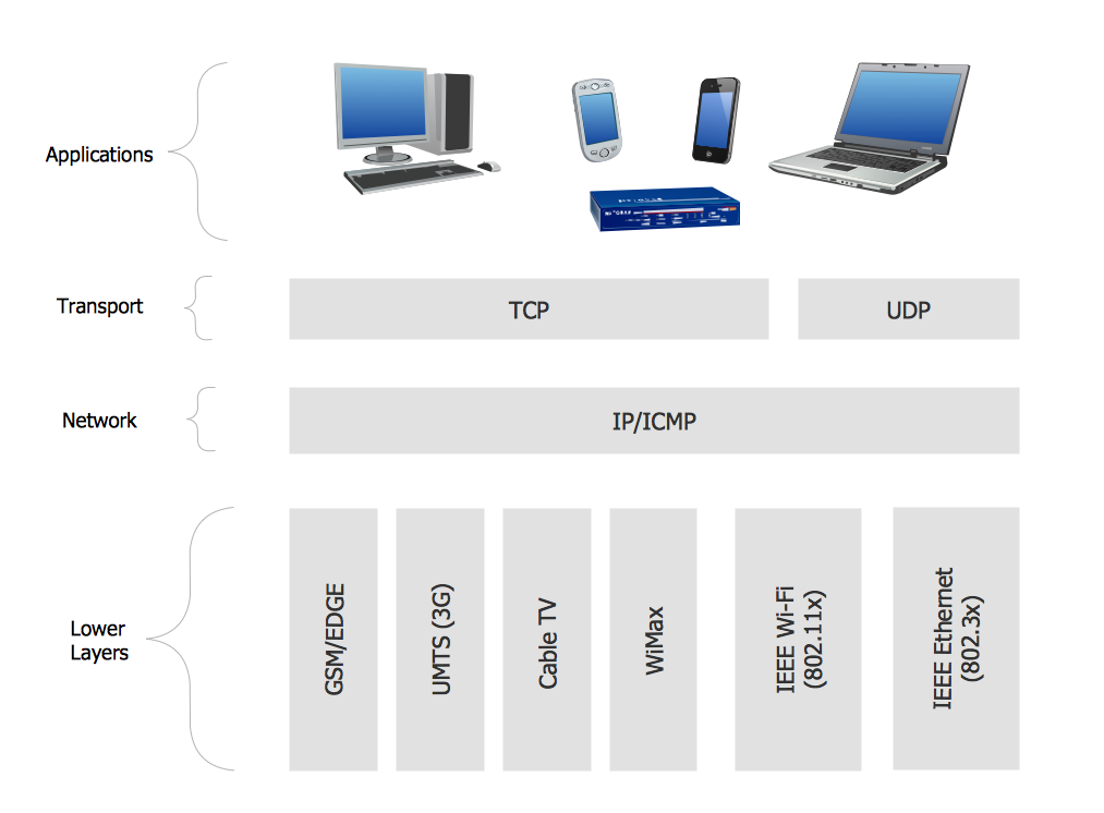
Example 1. Network protocols.
This sample diagram of computer network based on various protocols (TCP/IP, UDP, IP/ICMP, GSM/EDGE, UMTS/3G, Cable TV, WiMAX, IEEEE WiFi (802.11x), IEEEE Ethernet (802.3x) ) is created using ConceptDraw DIAGRAM diagramming and vector drawing software enhanced with Computer & Networks solution from ConceptDraw Solution Park.
Computer & Networks solution provides templates, samples and libraries of symbols for network floor plan layouts, network communication plans, Cisco network diagrams, Active Directory diagrams, logical network diagrams, LAN and WAN topology and design diagrams.
TEN RELATED HOW TO's:
ConceptDraw DIAGRAM is perfect for software designers and software developers who need to draw Computer&Network Diagrams.
ConceptDraw has 1004 vector stencils in the 40 libraries that helps you to start using software for designing own Network Diagrams. You can use the appropriate stencils from Computer and Network Diagrams library with 56 objects..png)
Picture: Design Element: Computer and Networkfor Network Diagrams
Related Solution:
Installing a wireless network is not very different from a regular network. After you configure the interfaces, the half of network configuration is done. You should also set routing, masquerading and set all the addresses.
This Interactive Voice Response Diagram (IVR) diagram depicts topology of an IVR system and shows physical and logical structure of an IVR system. It is created using facilities of the ConceptDraw solutions: Computer and Networks Diagrams in conjunction with Interactive Voice Response Diagrams. The diagram helps to understand how the call-center's equipment interacts with customer's calls to route them in the proper manner enabling client to get a useful response.
Picture: Network Configuration
Related Solution:
ConceptDraw DIAGRAM diagramming and vector drawing software provides the Telecommunication Network Diagrams Solution from the Computer and Networks Area for quick and easy drawing the Telecommunications Networks.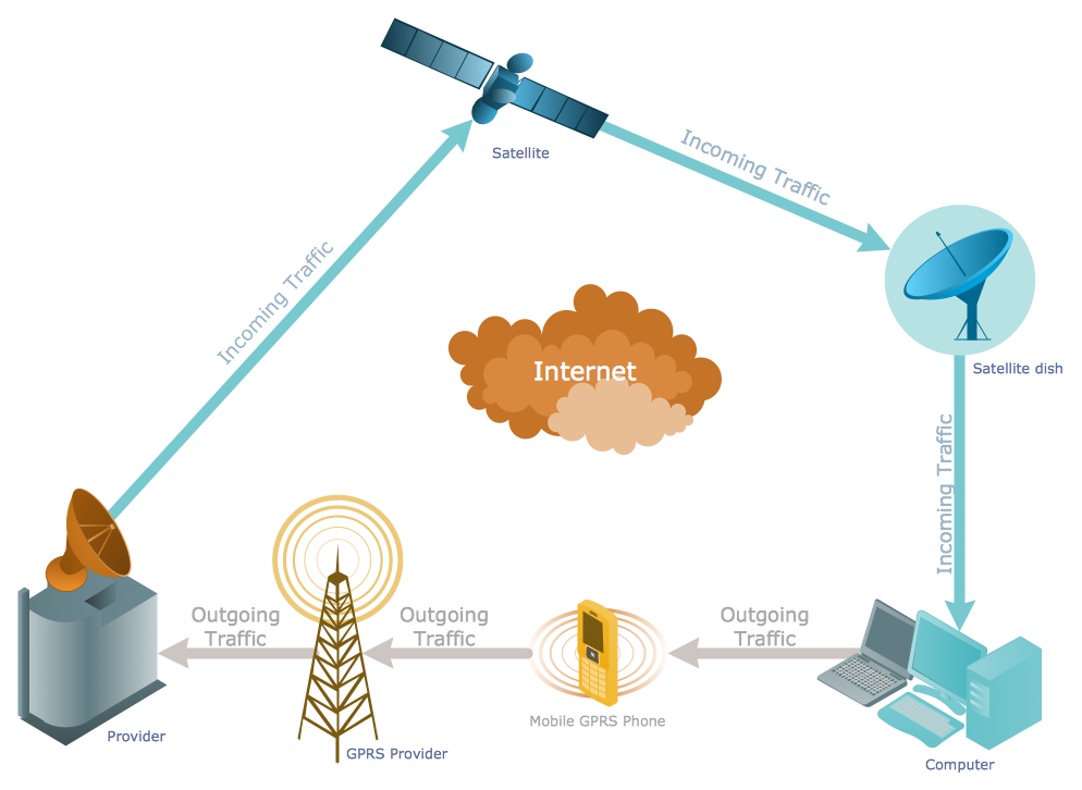
Picture: Telecommunications Networks
Related Solution:
ConceptDraw Wireless network diagrams help you to clearly represent and communicate the architecture, topology, and design of your wireless networks to engineers, stakeholders and end-users.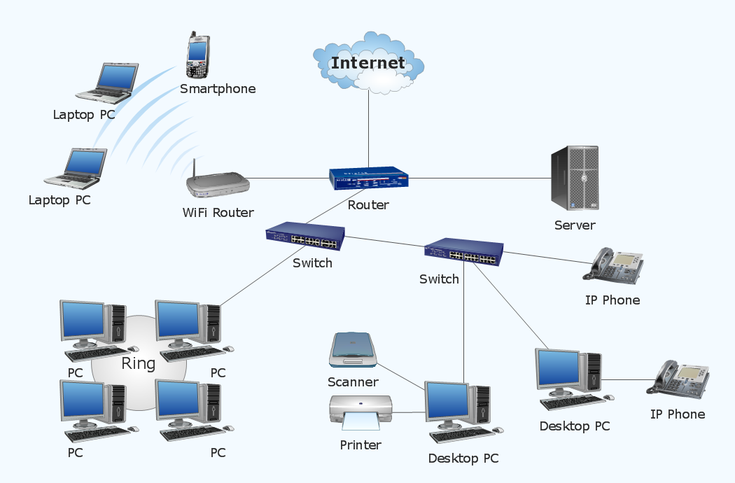
Picture: Troubleshooting in Wireless Connection
Related Solution:
Electrical Engineering Solution used together with ConceptDraw DIAGRAM drawing facilities makes short a work of drawing various electrical and electronic circuit schemes. A library of vector objects composed from symbols of Analog and Digital Logic elements of electric circuit includes 40 symbolic images of logic gates, bistable switches of bi-stable electric current, circuit controllers, amplifiers, regulators, generators, etc. All of them can be applied in electronic circuit schemes for showing both analog and digital elements of the circuit.
Electrical Engineering Solution used together with ConceptDraw DIAGRAM drawing facilities makes short a work of drawing various electrical and electronic circuit schemes. A library of vector objects composed from symbols of Analog and Digital Logic elements of electric circuit includes 40 symbolic images of logic gates, bistable switches of bi-stable electric current, circuit controllers, amplifiers, regulators, generators, etc. All of them can be applied in electronic circuit schemes for showing both analog and digital elements of the circuit.
Picture:
Electrical Diagram Symbols F.A.Q.
How to Use Electrical ConceptDraw Diagram Software
Related Solution:
ConceptDraw DIAGRAM is the best software for illustration the network topologies. It's very easy and quickly to design the network topology diagrams of any kinds and complexity in ConceptDraw DIAGRAM diagramming and vector drawing software using the Computer and Networks solution from Computer and Networks area of ConceptDraw Solution Park.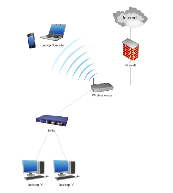
Picture: Network Topology Illustration
Related Solution:
Active Directory Diagrams visualize the detailed structures of the Microsoft Windows networks, Active Directory Domain topology, the Active Directory Site topology, the Organizational Units (OU), and the Exchange Server Organization.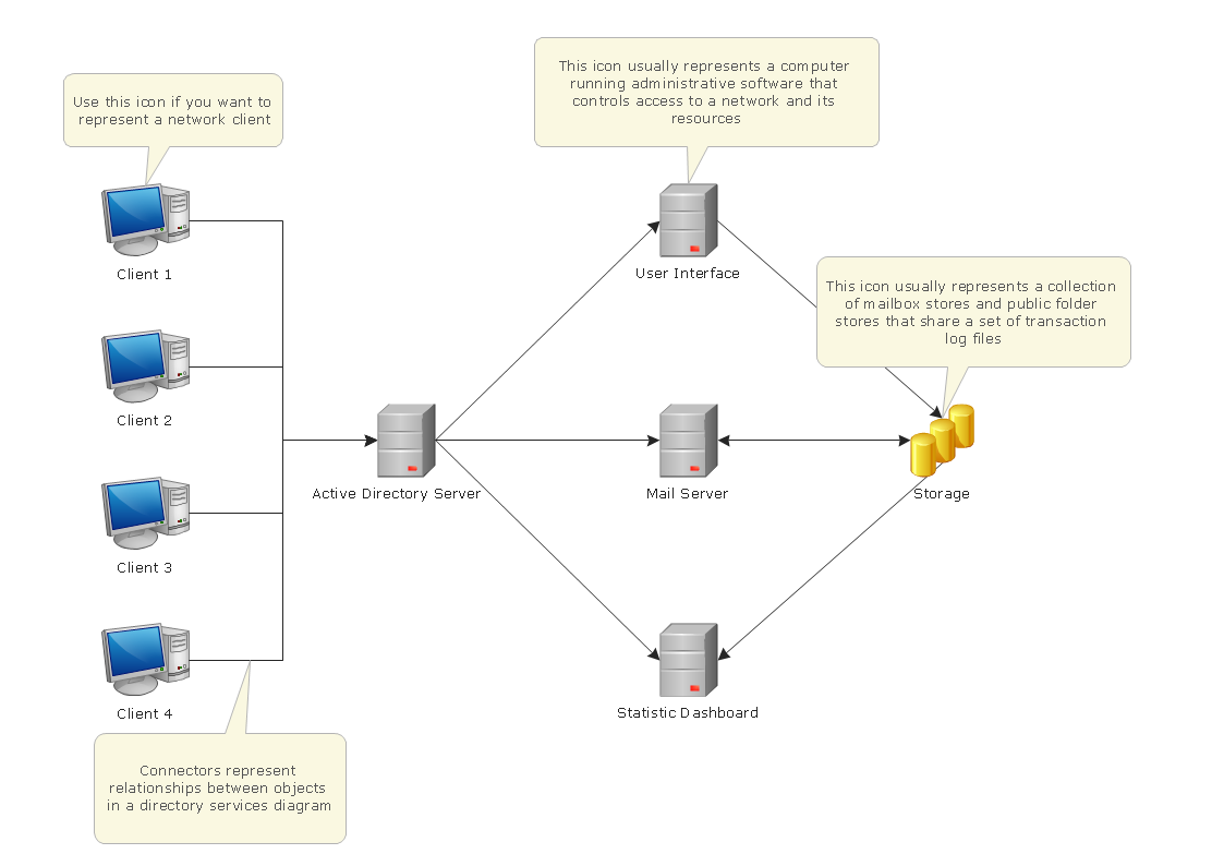
Picture: Active Directory Domain Services
ConceptDraw Network Diagram Software is ideal for network engineers and network designers who need to draw Physical Network Diagrams.
Picture: Network Diagram SoftwarePhysical Network Diagram
With best content of the Wireless Network solution that includes more than 10 building pre-designed objects network engineers can illustrate the computer network of a building.
Picture: Illustrate the Computer Network of a Building
Related Solution:
Any wireless network is some computer network that can use any needed wireless data connections that can be placed between the network nodes. Any wireless networking is known to be one of the methods by which both telecommunications networks and business installations, same as the homes avoid the process of introducing the cables into some building.
Drawing some wireless computer network as it may be a challenge, especially for those who do not have as much experience of doing it. That is why the CS Odessa team has developed the Wireless Networks solution so it can be used for simplifying all the ConceptDraw DIAGRAM users work on the needed diagrams.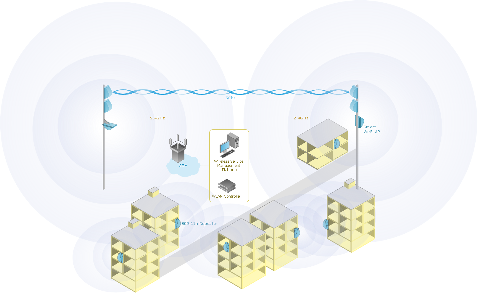
Picture: Calculate the cost of creating or updating a wireless computer network
Related Solution: