Wireless Network Diagram Examples
The ConceptDraw DIAGRAM is a best wireless network diagramming software. Wireless Network solution includes several wireless network diagram examples that users can modify and make your own diagram. TheConceptDraw DIAGRAM software helps users to quickly transition from an idea to the implementation of a wireless computer network.
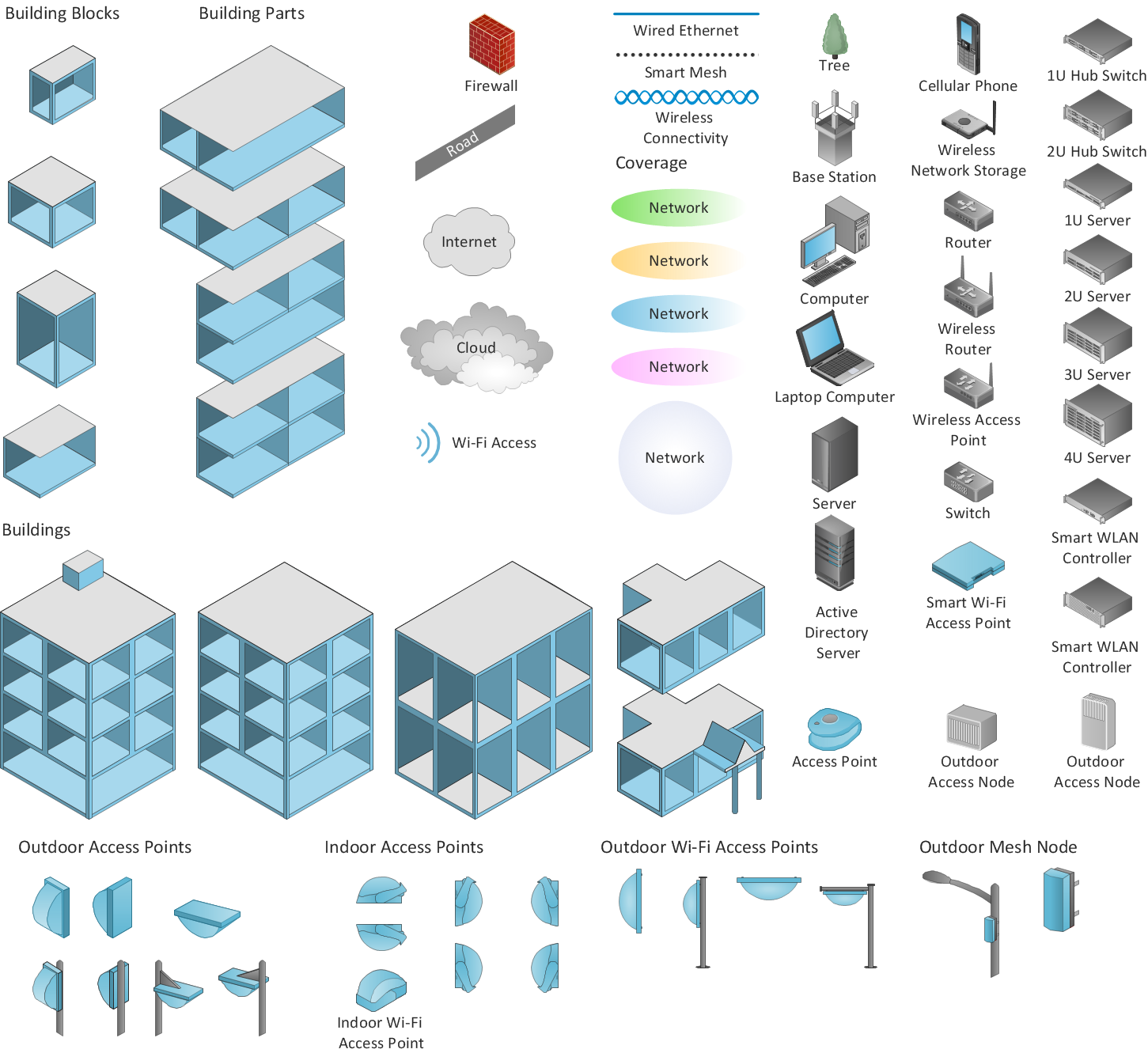
Sample 1. Design elements of wireless network diagram.
Wireless Network solution contains template, samples and a library of vector stencils that extends ConceptDraw Pro diagramming software functionality in order to help network engineers visualize Wireless Network. Network engineers and designers use this solution to design, create and illustrate the wireless computer networks.
See also Video:
How to Draw a Computer NetworkTEN RELATED HOW TO's:
Draw your own business process flowcharts using ConceptDraw DIAGRAM diagramming and business graphics software.
The Flowcharts Solution for ConceptDraw DIAGRAM is a comprehensive set of examples and samples in several different color themes for professionals that need to graphically represent a process.
Picture: Flow Chart Diagram Examples
Related Solution:
Fishbone, Ishikawa or Cause and Effect diagram helps understand the reasons of completed or potential actions by structuring their causes in smaller categories. Also, one can use it to see how the contributing factors are related to each other. In everyday company routine, a Cause and Effect diagram is helpful with a number of regular activities like brainstorming, project management, and problem solving.
How to Construct a Fishbone Diagram? Construction a Fishbone diagram in professional diagramming software ConceptDraw DIAGRAM is more easy than you think. Just use the predesigned vector elements from the Fishbone Diagrams library for Fishbone Diagrams solution or one of plenty Fishbone templates and examples, and you will get a Cause and Effect diagram in minutes.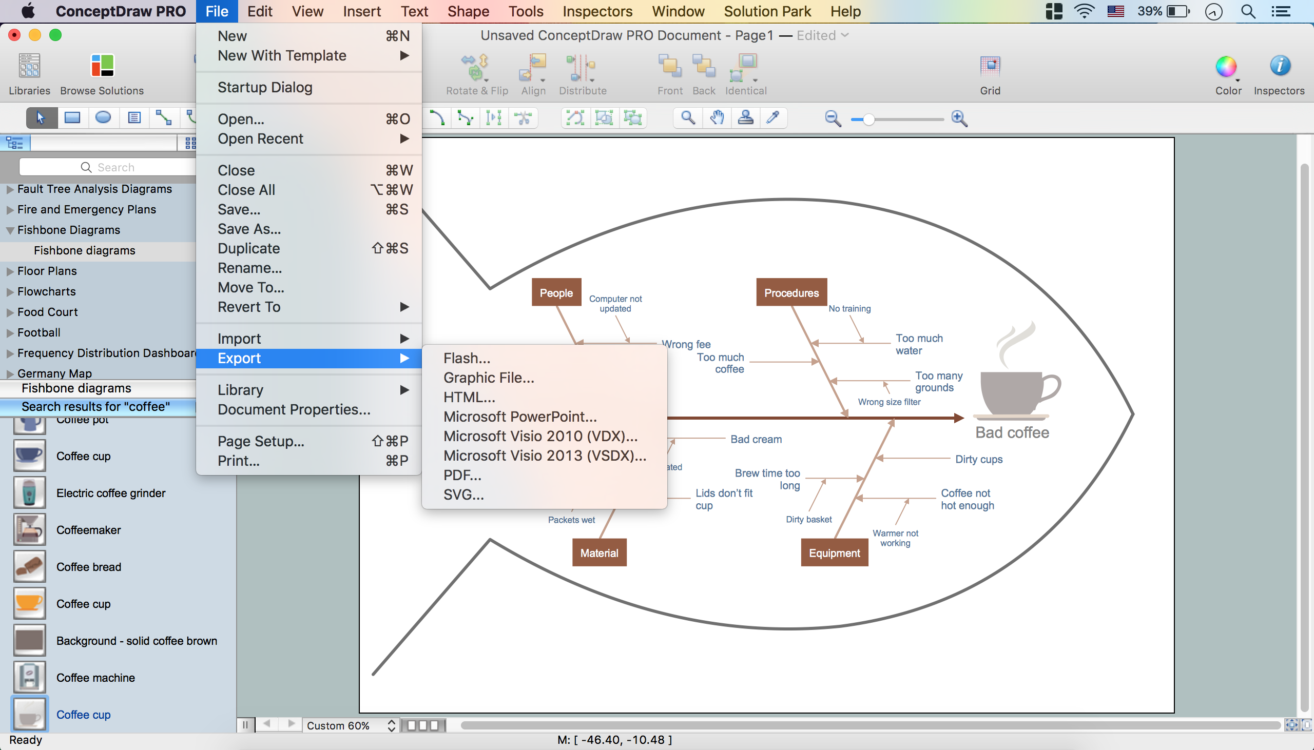
Picture: How to Construct a Fishbone Diagram
Related Solution:
Cafe Decor is one of the most important components of cafe design. Just thanks to the cafe decor elements is created the unique warm atmosphere of the cafe which makes you come back there again and again. ConceptDraw DIAGRAM extended with Cafe and Restaurant Floor Plan solution can help you create Cafe Decor designs simply and fast.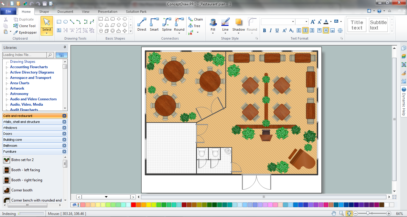
Picture: Cafe Decor
Related Solution:
Multiprotocol Label Switching (MPLS) is a mechanism in high-performance telecommunication networks that implements the data transfer from one network node to another using the labels.
ConceptDraw DIAGRAM is a powerful network diagramming and vector drawing software that provides the Computer and Networks solution with wide set of ready-to-use predesigned vector stencils and examples to help you design the MPLS Networks quick and easy.
Picture: Multiprotocol Label Switching (MPLS). Computer and Network Examples
Related Solution:
Planning a computer network can be a challenge for a junior specialist. However, knowing how to draw a computer network diagrams isn’t a rocket science anymore. There are a lot of special software for creating such diagrams with predesigned templates and examples.
The core for Network Fault Tolerance System presented here, is the equipment of Cisco. You can see here the certified Cisco equipment icons. Generally, ConceptDraw DIAGRAM libraries contain more than half of a thousand objects representing the standardized images of Cisco equipment. ConceptDraw solution for network diagramming is a great network diagramming tool for any level skills - from students to network guru.
Picture: How to Draw a Computer Network Diagrams
Related Solution:
Wireless Networks solution from ConceptDraw Solution Park extends ConceptDraw DIAGRAM diagramming software to help network engineers and designers efficiently design, create and illustrate wireless network diagrams.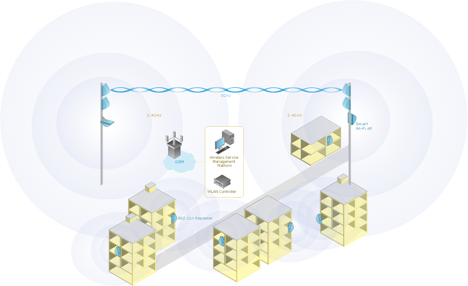
Picture: Wireless Network with ConceptDraw DIAGRAM
Related Solution:
Office design must to be well thought-out. It is especially important for the small offices, where each detail is in sight. ConceptDraw DIAGRAM software offers you the Office Layout Plans Solution from the Building Plans Area for quick and easy creating detailed Small Office Design plans.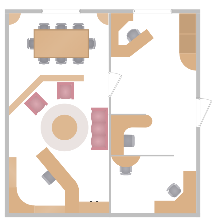
Picture: Small Office Design
Related Solution:
Any modern hotel must have a working computer network and a wifi network, allowing for Internet access for both clients and employees. Designing such networks first requires drawing a hotel network topology diagram, which is a type of a network diagram representing the physical graph of network nodes and connections. Modern digital drawing tools like ConceptDraw DIAGRAM include many templates of the different parts of a network diagram, such as hotel guest-house wifi network, to help you with this task.
Picture: Hotel Network Topology Diagram. Hotel Guesthouse WiFi Network
Related Solutions:
OSPF is an interior gateway protocol (IGP), it is widely used in large enterprise networks. OSPF routes the IP packets within a single routing domain. It gathers the information about the link state from the routers and makes the network topology map.
This example was created in ConceptDraw DIAGRAM using the Computer and Networks Area of ConceptDraw Solution Park and shows the OSPF diagram.
Picture: OSPF Network. Computer and Network Examples
Related Solution:
ConceptDraw DIAGRAM is the only application on the Macintosh platform, supplied with a comprehensive Cisco icon set. For graphic solutions that support Windows, only Microsoft Visio has a library of Cisco shapes. ConceptDraw DIAGRAM is a valuable option to many network professionals that use Macintosh computers or work in a combined Mac and PC environment.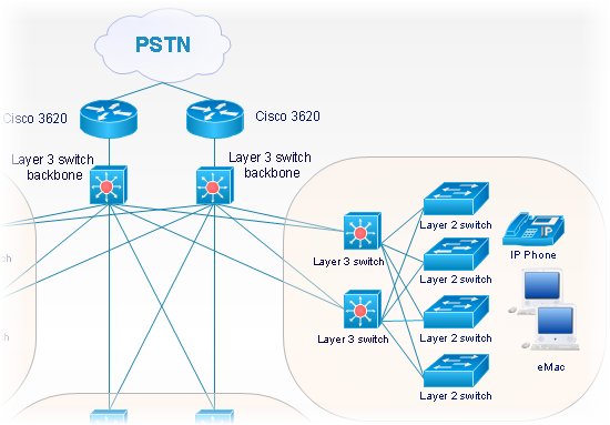
Picture: Cisco Network Objects in ConceptDraw DIAGRAM
ConceptDraw
DIAGRAM 18