Made with
ConceptDraw
DIAGRAM 18

Cisco Network Objects in ConceptDraw DIAGRAM

"Cisco customers generally use Visio or ConceptDraw to document their complex network designs. Cisco SE's such as myself use Visio or ConceptDraw to show customers new Cisco solutions that solve their business and network problems. So, I use ConceptDraw regularly for sales activities as I work in the sales division at Cisco." - Brad Hedlund, Systems Engineer at Cisco Systems

Read more user stories

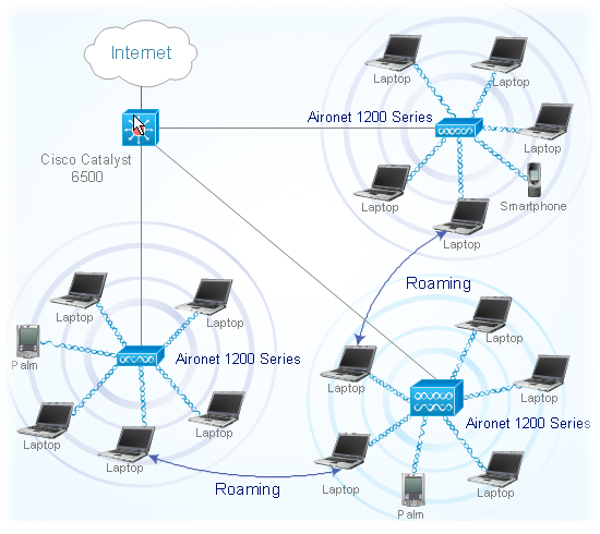
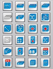
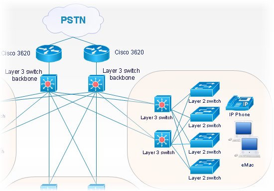
More than 400 network objects are contained in the ConceptDraw library. Our library is constructed in accordance with Cisco Systems Corporate iconography. All objects are vector, so they can be resized without losing any quality. Such an extensive library provides Network Professionals with the tools necessary to design and prepare network solution diagrams.

ConceptDraw Cisco Library Set contains the following libraries:

  • Basic elements - routers, switches, etc. 62 objects.
  • Buildings - office, university, government, etc. 20 objects.
  • IBM - mainframes, controllers, processors, etc. 7 objects.
  • LAN - workstations, terminals, servers, etc. 21 objects.
  • Media - token rings, FDDI rings, lines. 10 objects.
  • Multimedia, voice, phones. 27 objects.
  • Optical - amplifier, router, APS, etc. 18 objects.
  • People (as symbolic images). 16 objects. Additional products - gateways, workstations, concentrators, etc. 128 objects. Routers. 22 objects. Security - secure routers, secure switches, secure catalyst switches, etc. 15 objects. Switches & Hubs. 24 objects. Telepresence - CTS 100, CTS 200, CTS 300. 7 objects. WAN - hubs, clouds, MUX, NAT, etc. 15 objects. Miscellaneous - satellites, modems, BBS and other. 26 objects.

ConceptDraw DIAGRAM is the only application on the Macintosh platform, supplied with a comprehensive Cisco icon set. For graphic solutions that support Windows, only Microsoft Visio has a library of Cisco shapes. ConceptDraw DIAGRAM is a valuable option to many network professionals that use Macintosh computers or work in a combined Mac and PC environment.

Cisco Network Objects in ConceptDraw DIAGRAM  *

NINE RELATED HOW TO's:
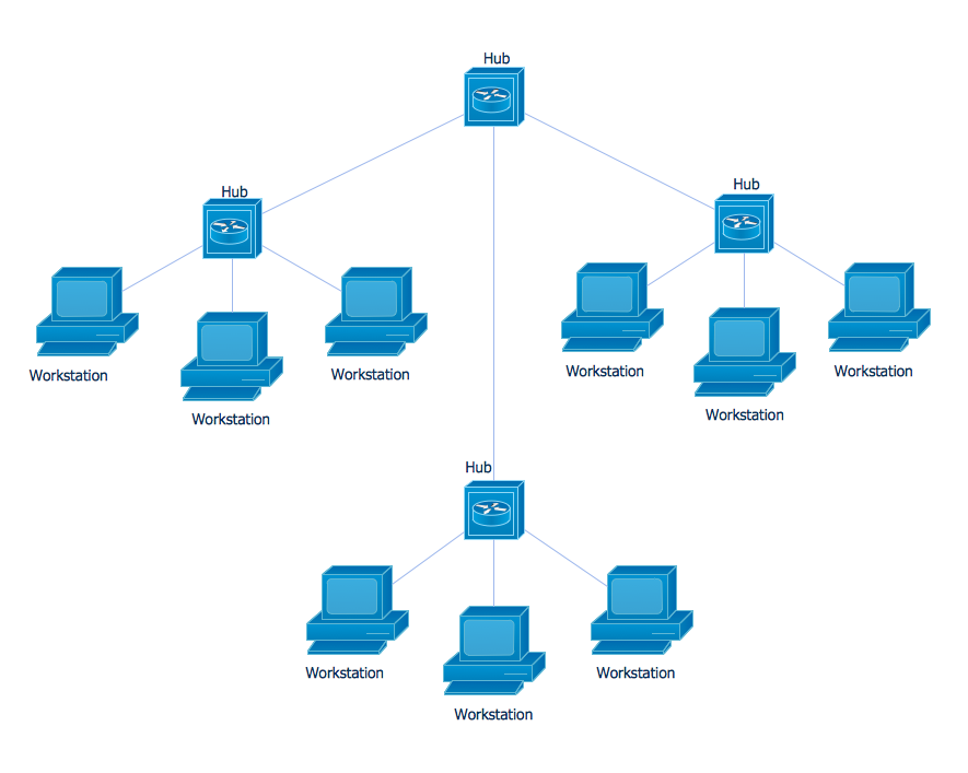
Nodes of any computer network are somehow organized in a hierarchy or a layout. Some of the common layouts like star network topology are more reliable and some like ring topology withstand high loads better. It is also important to distinguish logical topologies from physical. This diagram represents a typical view of the star network topology. The star network topology is one of the most frequently used network topologies in the majority of office and home networks. It is very popular because of its low cost and the easy maintenance. The plus of the star network topology is that if one computer on the local network is downed, this means that only the failed computer can not send or receive data. The other part of the network works normally. The minus of using star network topology is that all computers are connected to a single point-switch, or hub. Thus, if this equipment goes down, the whole local network comes down.Star Network Topology *
Picture: Star Network Topology
Related Solution:
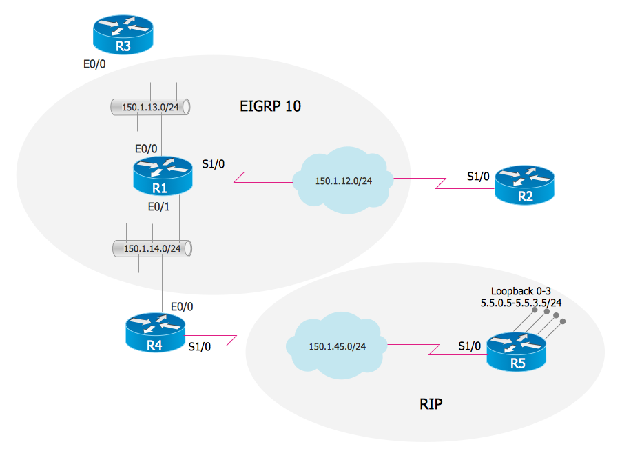
The Enhanced Interior Gateway Routing Protocol (EIGRP) is a progressive distance-vector dynamic routing protocol. It was developed by the Cisco Systems and is available as an open standard from 2013. EIGRP is used to help automate routing decisions and configuration of the computer network. It allows the routers of the same logical area automatically share route information.EIGRP. <br>Computer and Network Examples *
Picture: EIGRP. Computer and Network Examples
Related Solution:
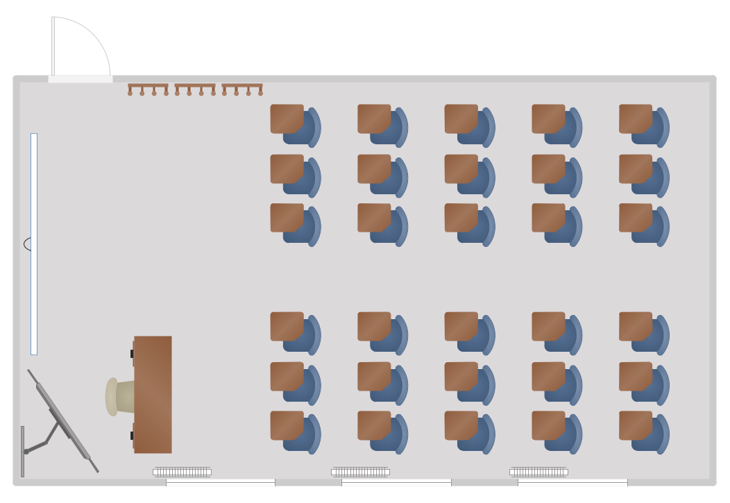
When developing the Classroom Seating Chart it is necessary to take into account the characteristics of the taken premises. Each seating place must to be comfortable and each pupil must to see good the teacher and the chalkboard. Let's design the Classroom Seating Chart in ConceptDraw DIAGRAM software extended with School and Training Plans Solution from the Building Plans Area.Classroom Seating Chart *
Picture: Classroom Seating Chart
Related Solution:
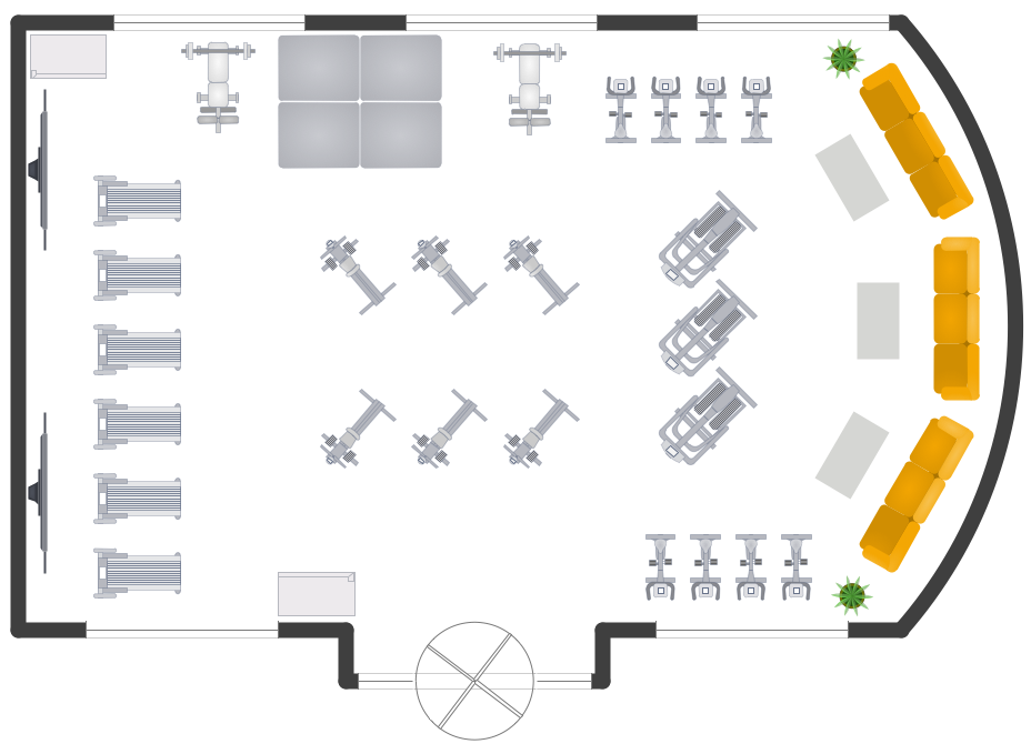
You need quickly design Gym Layout Plan? ConceptDraw DIAGRAM software supplied with Gym and Spa Area Plans solution from Building Plans area of ConceptDraw Solution Park will help you to handle this task.Gym Layout *
Picture: Gym Layout
Related Solution:
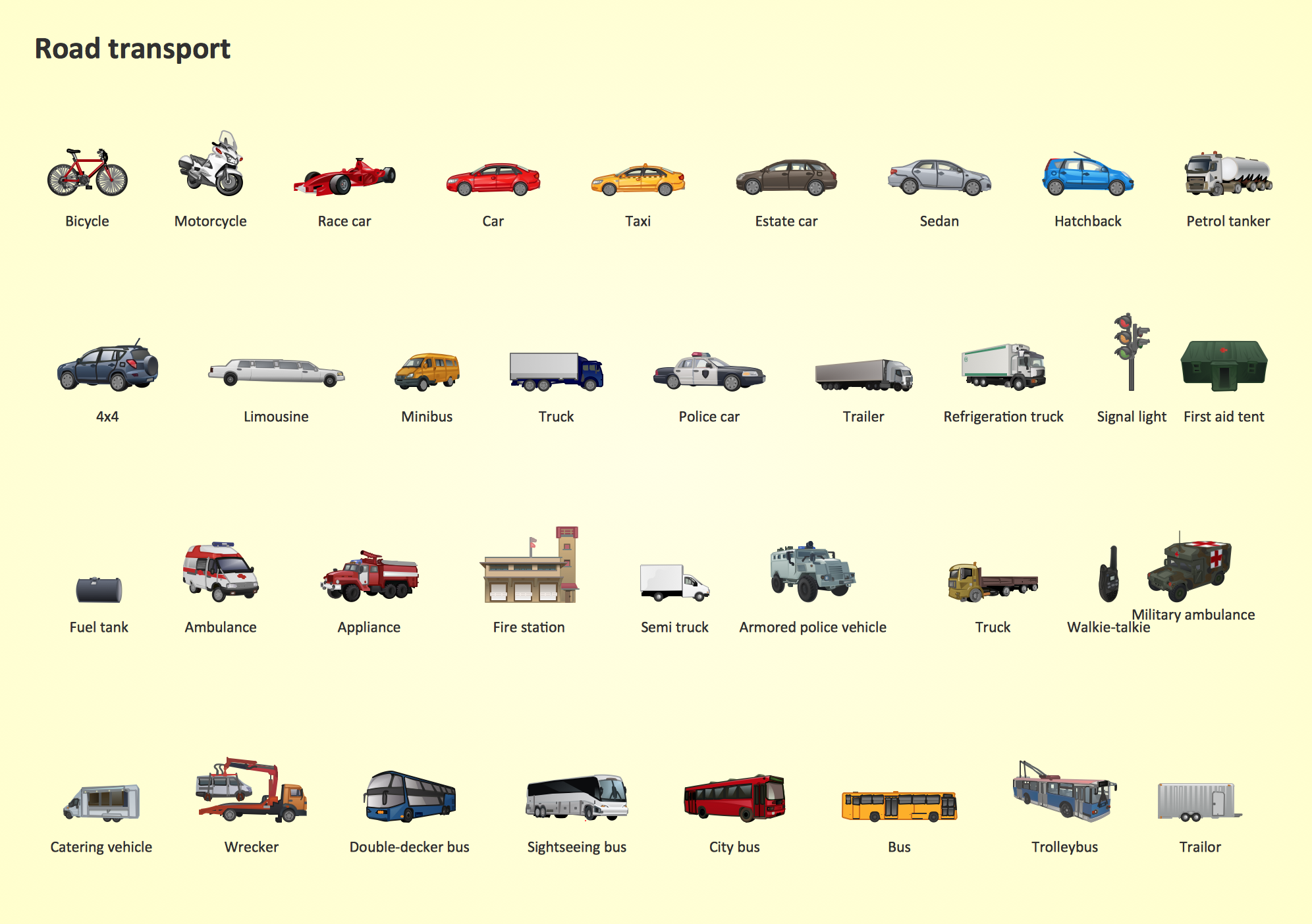
Samples, templates and libraries contain vector clip art for drawing the Road Transport Illustrations.Road Transport - Design Elements *
Picture: Road Transport - Design Elements
Related Solution:
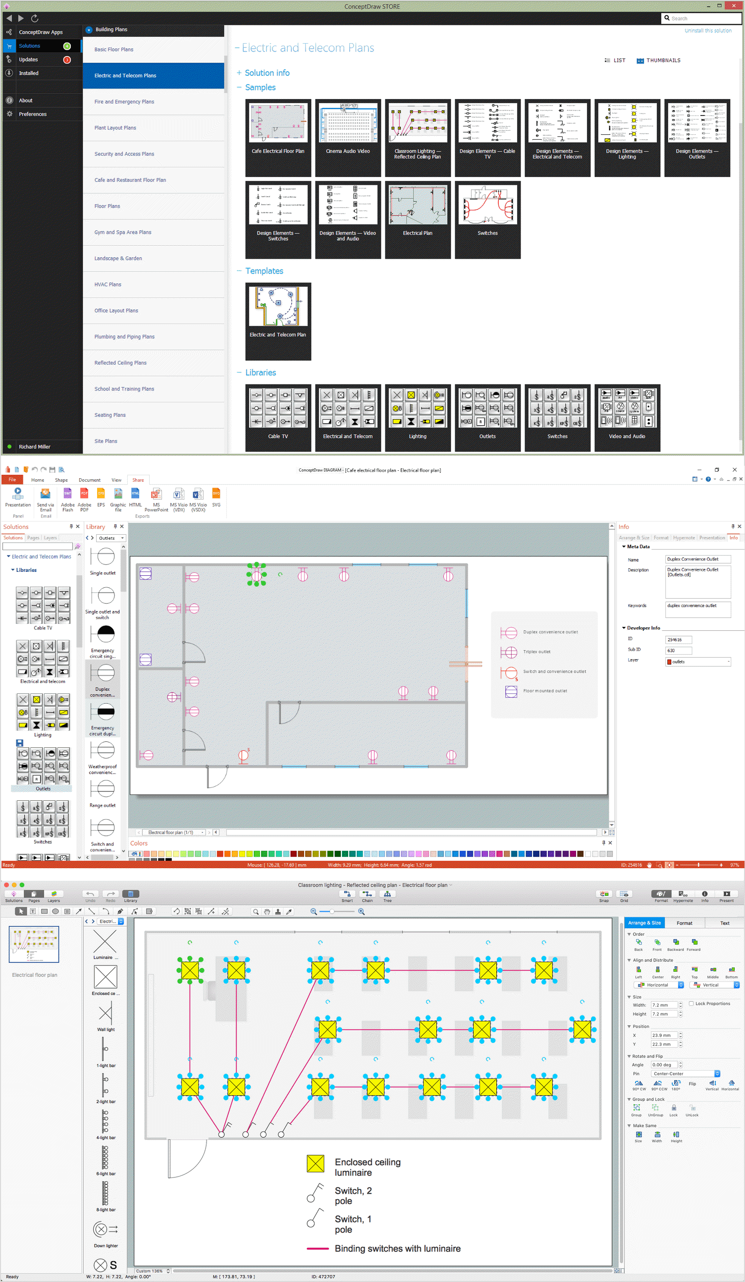
Electrical plan is a document that is developed during the first stage of the building design. This scheme is composed of conventional images or symbols of components that operate by means of electric energy. To simplify the creation of these schemes you can use house electrical plan software, which will not require a long additional training to understand how to use it. You only need to install the necessary software ant it’s libraries and you’ll have one less problem during the building projection. Any building contains a number of electrical systems, including switches, fixtures, outlets and other lightening equipment. All these should be depicted in a building electrical plans and included to general building documentation. This home electrical plan displays electrical and telecommunication devices placed to a home floor plan. On the plan, each electrical device is referenced with the proper symbol. Electrical symbols are used for universal recognition of the building plan by different persons who will be working on the construction. Not all possible electric symbols used on a certain plan, so the symbols used in the current home plan are included to a legend. The electrical home plan may be added as a separate document to a complete set of building plans.House Electrical Plan Software
Picture: How To use House Electrical Plan Software
Related Solution:
ConceptDraw Business Finance Illustration examples and libraries contain vector clip art for drawing different Business and Finance Illustrations. You may find Advertising example, Project Management example, Business Model example and many more.Business and Finance Illustrations Example *
Picture: Business and Finance Illustrations Example
Related Solution:
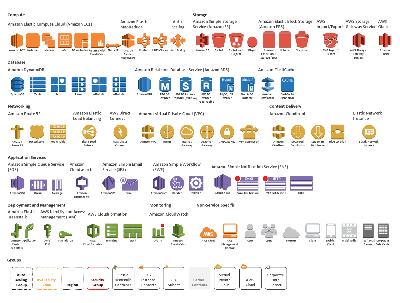
Succeed in AWS architecture design, communication and collaboration with a team. 🔸 Create detailed and always up-to-date ✔️ AWS diagrams, ✔️ infrastructure based on AWS services, ✔️ auto-scalable architectures, ✔️ AWS-based applicationsAWS icons  2.0
Picture: AWS icons 2.0
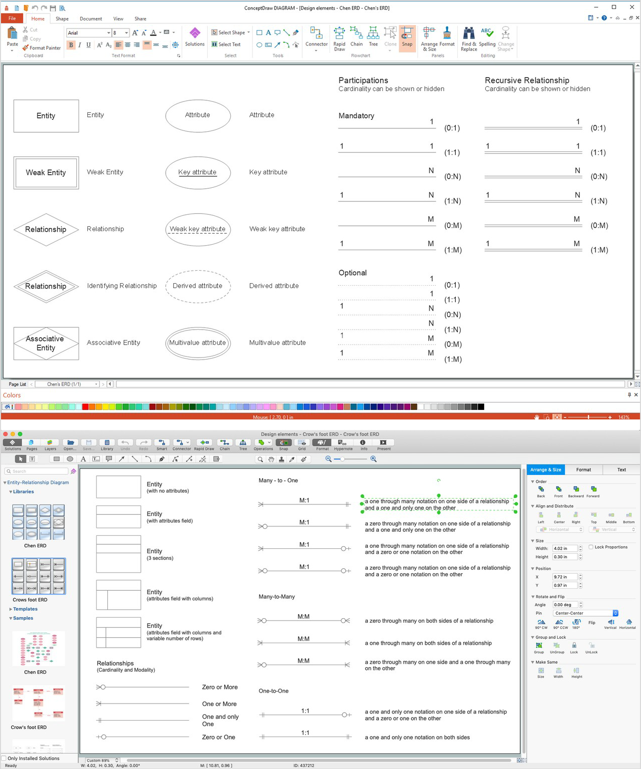
A database is a data collection, structured into some conceptual model. Two most common approaches of developing data models are UML diagrams and ER-model diagrams. There are several notations of entity-relationship diagram symbols and their meaning is slightly different. Crow’s Foot notation is quite descriptive and easy to understand, meanwhile, the Chen notation is great for conceptual modeling. An entity relationship diagrams look very simple to a flowcharts. The main difference is the symbols provided by specific ERD notations. There are several models applied in entity-relationship diagrams: conceptual, logical and physical. Creating an entity relationship diagram requires using a specific notation. There are five main components of common ERD notations: Entities, Actions, Attributes, Cardinality and Connections. The two of notations most widely used for creating ERD are Chen notation and Crow foot notation. By the way, the Crow foot notation originates from the Chen notation - it is an adapted version of the Chen notation.ERD Symbols and Meanings
Picture: ERD Symbols and Meanings
Related Solution:
ConceptDraw
DIAGRAM 18