WLAN
Making the WLAN schemes and diagrams is what sometimes the jobs might require. To complete such task, you can always use the ConceptDraw DIAGRAM diagramming and drawing software which was developed especially for people with such needs. There is also the so-called “Wireless Networks” solution placed in the ConceptDraw STORE application that can be useful for making the mentioned drawings.
WLAN is an abbreviation for the “wireless local area network”. It is a wireless computer network that links two or more than two devices with each other by using the wireless communication within some limited area such as school, home, office building or computer laboratory. Having WLAN means having an opportunity to use this great opportunity to move around within some local coverage area. Through a special gateway, any WLAN can also provide the needed connection to the wider Internet.

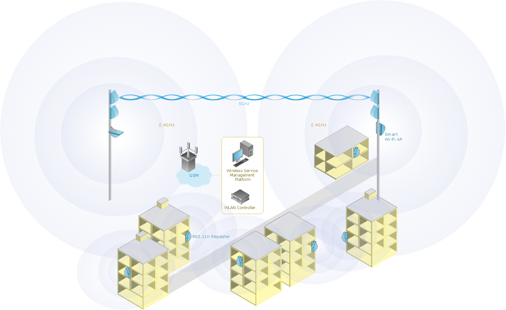
Example 1. Wireless Networks Solution in ConceptDraw STORE
Most modern WLANs are known to be based on the IEEE 802.11 standards. They are marketed under the “Wi-Fi” brand name. The Wireless LANs have become popular quite recently for use at home, due to the simplicity of use or installation. Such WLANs are also very popular in the commercial properties that offer the wireless access to their customers so they can use it for free.
Wireless LANs have lots of applications and all the modern implementations of WLANs can be small in-home networks as well as the large one, campus-sized ones to completely mobile networks on trains and airplanes. All the users can access the Internet from different WLAN hotspots in hotels, restaurants and also with portable devices that connect to either 4G or 3G networks.
Quite often such types of the public access points do not require any registration or even a password in order to join the needed network. At the same time, there are the other ones that can be accessed only in case the registration has occurred or some fixed fee is paid. All the existing Wireless LAN infrastructures can also be used for working as the indoor positioning systems having no modification to the existing hardware.
There are two definitions for the wireless LAN roaming, first of which is the Internal Roaming. In this case, the Mobile Station moves from one access point to another AP within some home network in case the signal strength is not strong enough. An authentication server is known to be performing the re-authentication of the previously mentioned Mobile Station via 802.1x.
In case of billing of QoS in the home network, a Mobile Station roams from one access point to another, interrupting the flow of data among an application that is connected to the network and the Mobile Station (MS). The last one has to periodically monitor the presence of the other, alternative access points in case they can provide any better connection.
At some point, the MS may decide to re-associate with an access point that has a stronger wireless signal, being based on the proprietary mechanisms. But in this case the Mobile Station may lose a connection with an access point before associating with another access one, so in terms of providing the reliable connections with applications, the MS must include the appropriate software that can provide the needed session persistence.
External Roaming can be another definition for the wireless LAN roaming. In this particular case, the Mobile Station moves into a wireless local area network of another Wireless Internet Service Provider, taking their services, known to be called as a “Hotspot”. Any user can use another foreign network independently of his home network in case it is open to other visitors but the owners. There should be special billing systems and the authentication to use for mobile services in any foreign network, though.
There are two basic modes of operation in IEEE 802.11. First of is the infrastructure and the second one is “ad hoc mode”. In the last one, the mobile units are known to be transmitting directly peer-to-peer. In the first one, the infrastructure one, such mobile units can communicate through the certain access points that serve as the bridges to other networks.
Because any wireless communication is known to be using a more open medium for communication to compare to the wired LANs, there are also the included encryption mechanisms that the 802.11 designers add, such as the Wired Equivalent Privacy and the Wi-Fi Protected Access in order to secure the wireless computer networks. There are many access points that can also offer the so-called Wi-Fi Protected Setup. The last mentioned is simply a quick method of joining any new device to the encrypted network.
Most of the Wi-Fi networks are known to be deployed in infrastructure mode and a base station there is known to be acting as a wireless access point hub. The nodes within it communicate through the hub and the hub itself has a special fiber or wired network connection, having the permanent wireless connections to other nodes. The wireless access points are usually fixed, known to be providing the needed service to their client nodes within some particular range.
The wireless clients are smartphones, laptops, tablets and other devices that connect to the access point in order to join the network itself. Sometimes such network has more than one access points, with the same security arrangement and “SSID”. In such case, it becomes possible to connect to any access point on that network as the client software may try to choose the access point in order to give the best service, such as the access point with the best, the strongest signal.
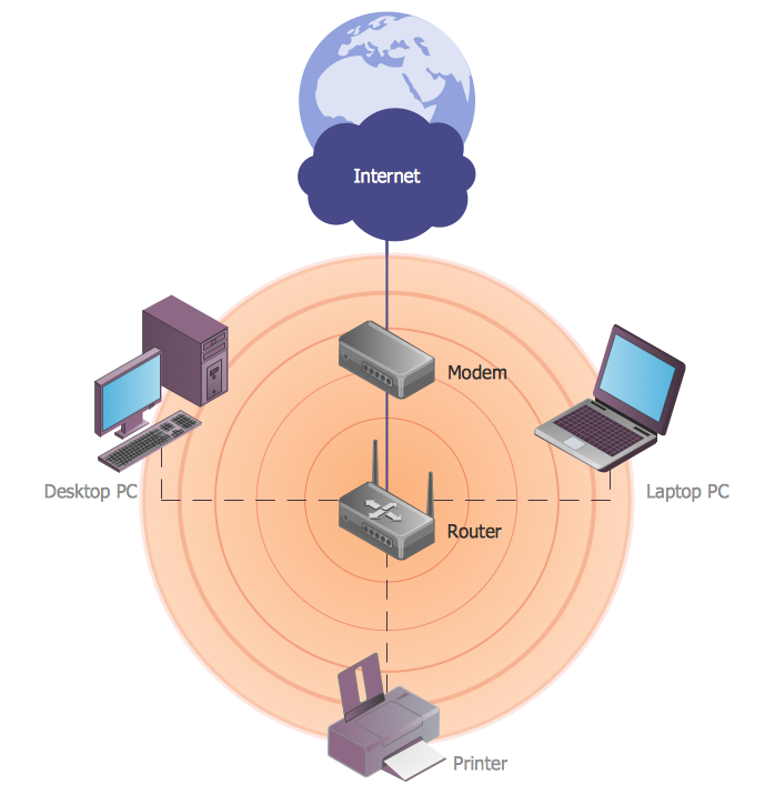
Example 2. WLAN — Wireless Local Area Network
Having the ConceptDraw DIAGRAM diagramming and drawing software as well as the Wireless Networks solution may lead to a great looking result of a professionally created WLAN diagrams by using the available stencil library with 81 wireless communications objects as well as the pre-made examples of the WLAN drawings.