Network Topologies


Network Topology Illustration

Physical network. Computer and Network Examples


Fully Connected Network Topology Diagram

Hybrid Network Topology

Mesh Network. Computer and Network Examples

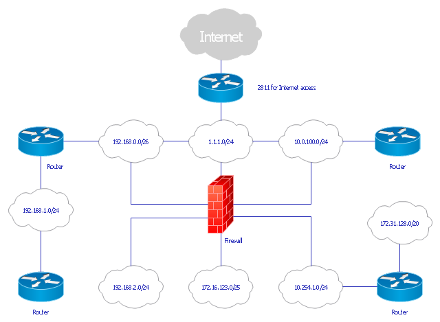
"... logical topology shows how data flows within a network, regardless of its physical design. ...
... mapping the data flow between the components determines the logical topology of the network." [Network topology. Wikipedia]
"In a shared media topology, all the systems have the ability to access the physical layout whenever they need it. The main advantage in a shared media topology is that the systems have unrestricted access to the physical media. Of course, the main disadvantage to this topology is collisions. If two systems send information out on the wire at the same time, the packets collide and kill both packets. Ethernet is an example of a shared media topology. ...
The token-based topology works by using a token to provide access to the physical media. In a token-based network, there is a token that travels around the network. When a system needs to send out packets, it grabs the token off of the wire, attaches it to the packets that are sent, and sends it back out on the wire. As the token travels around the network, each system examines the token. When the packets arrive at the destination systems, those systems copy the information off of the wire and the token continues its journey until it gets back to the sender. When the sender receives the token back, it pulls the token off of the wire and sends out a new empty token to be used by the next machine." [Logical topology. Wikipedia]
This Cisco logical computer network diagram example was created using the ConceptDraw PRO diagramming and vector drawing software extended with the Cisco Network Diagrams solution from the Computer and Networks area of ConceptDraw Solution Park.
Logical network diagram
Metropolitan area networks (MAN). Computer and Network Examples
. Computer and Network Examples")
Bus Network Topology

Network Topology

 Computer Network Diagrams
Computer Network Diagrams solution extends ConceptDraw DIAGRAM software with samples, templates and libraries of vector icons and objects of computer network devices and network components to help you create professional-looking Computer Network Diagrams, to plan simple home networks and complex computer network configurations for large buildings, to represent their schemes in a comprehensible graphical view, to document computer networks configurations, to depict the interactions between network's components, the used protocols and topologies, to represent physical and logical network structures, to compare visually different topologies and to depict their combinations, to represent in details the network structure with help of schemes, to study and analyze the network configurations, to communicate effectively to engineers, stakeholders and end-users, to track network working and troubleshoot, if necessary.
Ring Network Topology

Computer Network. Computer and Network Examples

Network Diagram Software Enterprise Private Network

Scrum process work items and workflow

SysML

Road Transport - Design Elements

Business Architecture

Structured Systems Analysis and Design Method. SSADM with ConceptDraw DIAGRAM

Components of ER Diagram

- Logical Topology Advantages And Disadvantages Of Logical
- Basic Network Diagram | Disadvantage Of Logical Topology
- Evalueta The Advantages And Disadvantages Of The Physical And ...
- Hybrid Network Topology | Star Network Topology | Wireless ...
- Fully Connected Topology Advantages And Disadvantages
- Star Network Topology | Bus Network Topology | Hybrid Network ...
- Microsoft Visio Pfd Advantages And Disadvantages
- Network Diagram Software Logical Network | Network Diagram ...
- Point to Point Network Topology | Bus Network Topology | Wireless ...
- Personal area (PAN) networks. Computer and Network Examples ...
- Advantages And Disadvantages Of Fault Analysis
- Advantages And Diaadvantages Of Epn
- Physical And Logical Network Layout
- Advantage And Disadvantage Personal Area Network
- Fully Connected Network Topology Diagram | Ring Network ...
- Advantages And Disadvantages Of Fault Tree Analysis
- Advantages And Disadvantages Of Metropolitan Area Network Pdf
- Cisco Network Templates | Azure Architecture | In searching of ...
- Wireless Network Topology | Star Network Topology | Hierarchical ...
- Wireless Network Topology | Hybrid Network Topology | Mesh ...