Local area network (LAN). Computer and Network Examples
 diagram")

"Logical topology, or signal topology, is the arrangement of devices on a computer network and how they communicate with one another. How devices are connected to the network through the actual cables that transmit data, or the physical structure of the network, is called the physical topology. Physical topology defines how the systems are physically connected. It represents the physical layout of the devices on the network. The logical topology defines how the systems communicate across the physical topologies.
Logical topologies are bound to network protocols and describe how data is moved across the network. ...
EXAMPLE : twisted pair Ethernet is a logical bus topology in a physical star topology layout. while IBM's token ring is a logical ring topology, it is physically set up in star topology." [Logical topology. Wikipedia]
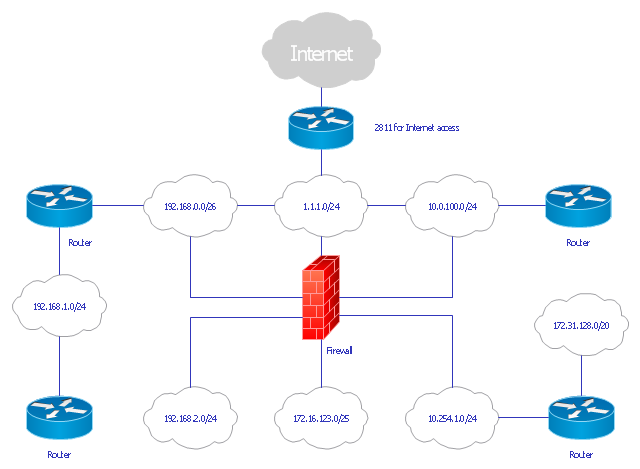
This Cisco logical computer network diagram example was created using the ConceptDraw PRO diagramming and vector drawing software extended with the Cisco Network Diagrams solution from the Computer and Networks area of ConceptDraw Solution Park.
Logical topologies are bound to network protocols and describe how data is moved across the network. ...
EXAMPLE : twisted pair Ethernet is a logical bus topology in a physical star topology layout. while IBM's token ring is a logical ring topology, it is physically set up in star topology." [Logical topology. Wikipedia]
This Cisco logical computer network diagram example was created using the ConceptDraw PRO diagramming and vector drawing software extended with the Cisco Network Diagrams solution from the Computer and Networks area of ConceptDraw Solution Park.
Logical network topology diagram

Network Diagram Software Physical Network Diagram

Network diagrams with ConceptDraw DIAGRAM

Network Diagram Software Logical Network Diagram

Network Topologies


 Computer Network Diagrams
Computer Network Diagrams solution extends ConceptDraw DIAGRAM software with samples, templates and libraries of vector icons and objects of computer network devices and network components to help you create professional-looking Computer Network Diagrams, to plan simple home networks and complex computer network configurations for large buildings, to represent their schemes in a comprehensible graphical view, to document computer networks configurations, to depict the interactions between network's components, the used protocols and topologies, to represent physical and logical network structures, to compare visually different topologies and to depict their combinations, to represent in details the network structure with help of schemes, to study and analyze the network configurations, to communicate effectively to engineers, stakeholders and end-users, to track network working and troubleshoot, if necessary.
Star Network Topology

Hotel Network Topology Diagram

 Cisco Network Diagrams
Cisco Network Diagrams solution extends ConceptDraw DIAGRAM with the best characteristics of network diagramming software. Included samples, templates and libraries of built-in standardized vector Cisco network icons and Cisco symbols of computers, network devices, network appliances and other Cisco network equipment will help network engineers, network designers, network and system administrators, as well as other IT professionals and corporate IT departments to diagram efficiently the network infrastructure, to visualize computer networks topologies, to design Cisco computer networks, and to create professional-looking Cisco Computer network diagrams, Cisco network designs and schematics, Network maps, and Network topology diagrams in minutes.
Design Element: Computer and Network for Network Diagrams
.png "Design Element: Computer and Network<br>for Network Diagrams *")
Network Diagram Software Topology Network

Virtual networks. Computer and Network Examples

Network Diagram Software. LAN Network Diagrams. Physical Office Network Diagrams


Network Diagram Software Logical Network

"A computer network or data network is a telecommunications network that allows computers to exchange data. In computer networks, networked computing devices pass data to each other along data connections. The connections (network links) between nodes are established using either cable media or wireless media. ...
Network computer devices that originate, route and terminate the data are called network nodes. Nodes can include hosts such as personal computers, phones, servers as well as networking hardware. Two such devices are said to be networked together when one device is able to exchange information with the other device, whether or not they have a direct connection to each other. ...
Users and network administrators typically have different views of their networks. Users can share printers and some servers from a workgroup, which usually means they are in the same geographic location and are on the same LAN, whereas a Network Administrator is responsible to keep that network up and running. A community of interest has less of a connection of being in a local area, and should be thought of as a set of arbitrarily located users who share a set of servers, and possibly also communicate via peer-to-peer technologies.
Network administrators can see networks from both physical and logical perspectives. The physical perspective involves geographic locations, physical cabling, and the network elements (e.g., routers, bridges and application layer gateways) that interconnect the physical media. Logical networks, called, in the TCP/ IP architecture, subnets, map onto one or more physical media. For example, a common practice in a campus of buildings is to make a set of LAN cables in each building appear to be a common subnet, using virtual LAN (VLAN) technology." [Computer network. Wikipedia]
The network layout floorplan template for the ConceptDraw PRO diagramming and vector drawing software is included in the Network Layout Floor Plans solution from the Computer and Networks area of ConceptDraw Solution Park.
Network layout floor plan template

Virtual private networks (VPN). Computer and Network Examples
. <br>Computer and Network Examples *")
"... logical topology shows how data flows within a network, regardless of its physical design. ...
... mapping the data flow between the components determines the logical topology of the network." [Network topology. Wikipedia]
"In a shared media topology, all the systems have the ability to access the physical layout whenever they need it. The main advantage in a shared media topology is that the systems have unrestricted access to the physical media. Of course, the main disadvantage to this topology is collisions. If two systems send information out on the wire at the same time, the packets collide and kill both packets. Ethernet is an example of a shared media topology. ...
The token-based topology works by using a token to provide access to the physical media. In a token-based network, there is a token that travels around the network. When a system needs to send out packets, it grabs the token off of the wire, attaches it to the packets that are sent, and sends it back out on the wire. As the token travels around the network, each system examines the token. When the packets arrive at the destination systems, those systems copy the information off of the wire and the token continues its journey until it gets back to the sender. When the sender receives the token back, it pulls the token off of the wire and sends out a new empty token to be used by the next machine." [Logical topology. Wikipedia]
This Cisco logical computer network diagram example was created using the ConceptDraw PRO diagramming and vector drawing software extended with the Cisco Network Diagrams solution from the Computer and Networks area of ConceptDraw Solution Park.
Logical network diagram
Cisco Network Topology. Cisco icons, shapes, stencils and symbols

- Network diagrams with ConceptDraw DIAGRAM | Network Diagram ...
- Physical Network Diagram Vs Logical
- Network Logical Diagram Example
- Diagram Physical Topologies | Physical LAN topology diagram ...
- Wide area network (WAN) topology . Computer and Network ...
- Logical network topology diagram | Network Diagram Software ISG ...
- Logical network topology diagram | Network Diagram Software ...
- Logical network topology diagram | Network Diagram Examples ...
- Network Diagram Software Logical Network Diagram | Network ...
- Network Diagram Software Logical Network Diagram | Network ...
- How To Interpret Network Diagram
- Network Diagram Examples | Network Diagram Software Logical ...
- Wireless access point | Hotel Network Topology Diagram | How to ...
- Logical network topology diagram | Physical Topology Diagrams ...
- Network Diagram Software Physical Network Diagram | Network ...
- Logical Network Diagrams
- Network Diagram Examples | Network Diagram Software Physical ...
- Logical network topology diagram | Network Topology Diagram
- Design Element: Network Layout for Network Diagrams | Network ...