What is a Virtual Private Network?VPN Diagram Examples
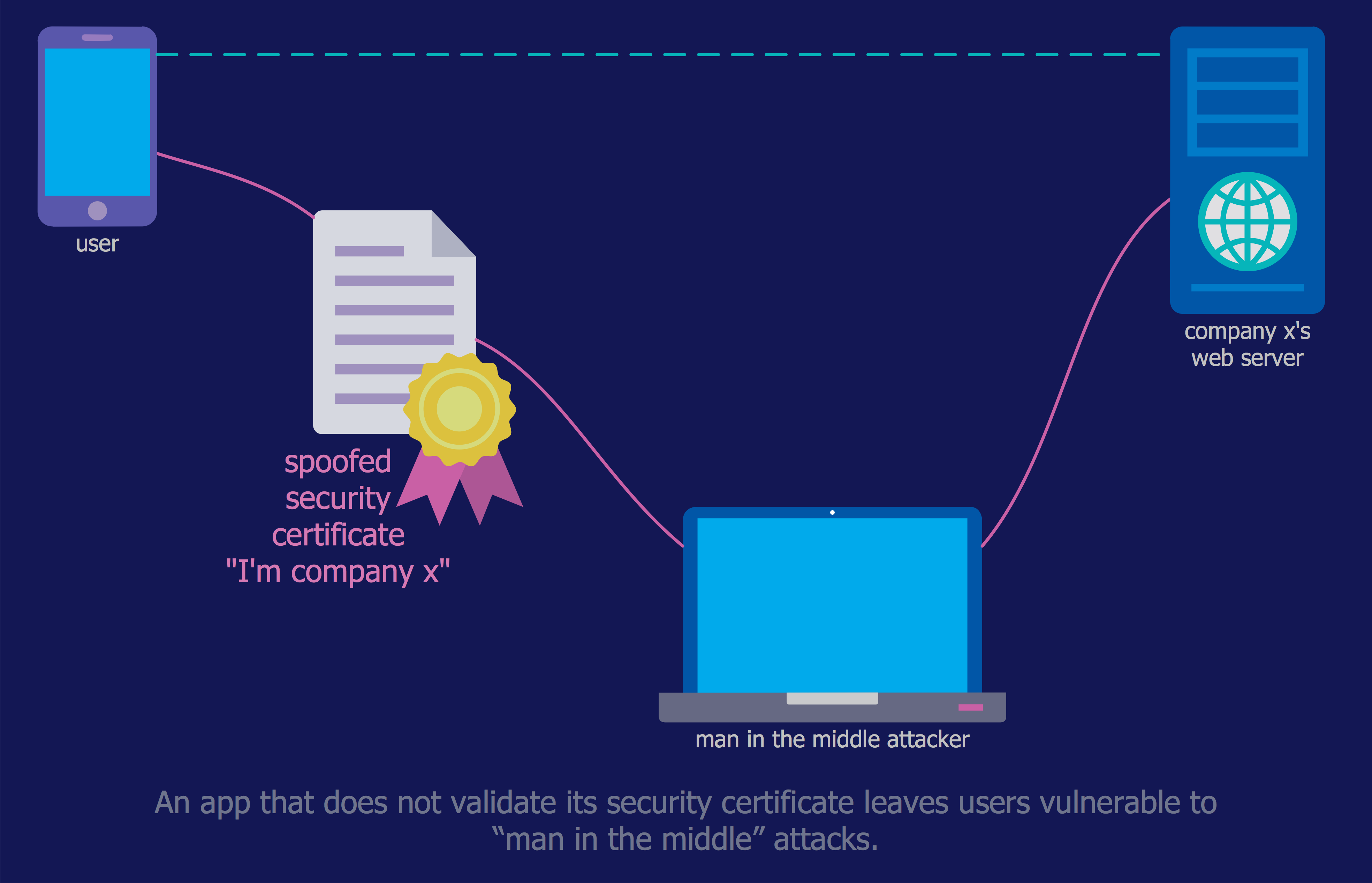
With the growing rate of cyber threats and cybercrime, users become more vulnerable to hacking and interception of private information and data, and using them for nefarious purposes. Moreover, some applications and websites can silently track your online movements. Therefore, the task of privacy and security, and protecting your actions, personal data, and sensitive information you enter online against tracking, gain more importance.
The users wonder what is virtual private network and how it is useful for them. Connectivity and secure access to the Internet are easily achieved by using a VPN, which masks your IP address through routing to a remote VPN server, 256-bit encryption of all transmitted data, and multi-factor authentication. This keeps your personal data private and prevents Internet Service Provider (ISP) tracking.
VPNs use different types of protocols to encrypt web connections and varied software. Currently, they are used on all electronic devices and are based mostly on IP and IP/Multiprotocol Label Switching (MPLS) Networks, earlier they used the Frame Relay and Asynchronous Transfer Mode (ATM) virtual circuits.
What is a Virtual Private Network
A Virtual Private Network (VPN) is a network that allows private networks at a remote location to connect securely to the public Internet and provide access for transmitting data only to the intended recipients. VPN is built by creating a virtual point-to-point connection using dedicated connections, technologies of traffic encryption, and virtual tunneling protocols.
VPN provides a safe and encrypted online connection between a computing device, even if it uses insecure public internet, and a computer network, or between two networks. Security starts with a VPN diagram and its implementation and is a sure way for users to get privacy and anonymity using the Internet, securely send and receive information and data across the Internet, ensure security using the corporative network remotely, or bypass geographic-based blocking.
As a rule, internet providers have access to information about customer's activities on the Internet. Moreover, unsecured Wi-Fi access points are susceptible to attackers who can track your activities online and gain access to personal data. VPN is a way to ensure security of actions on the Internet and safety of personal data and important information. VPNs protect you through the real-time encryption of internet traffic, masking your IP address, and disguising your online identity. They create a point-to-point tunnel and establish a digital connection between your computer and a remote server of a VPN provider.
VPN benefits and disadvantages
VPNs provide a lot of benefits for their users. These include:
| # | Benefits |
|---|---|
| 1. | Online anonymity |
| 2. | Secure connectivity |
| 3. | Security of sending and receiving data |
| 4. | Safety, privacy, and integrity of information |
| 5. | Ability to browse more safely on public Wi-Fi |
| 6. | Use online banking more safely from anywhere |
| 7. | Simplified distributed networks access control |
| 8. | Collaboration and connectivity between teams, networks, and offices in different geographical areas |
| 9. | Network scalability, support, and flexibility for remote workers through secure and seamless remote access to corporate networks and resources, software applications in a secure cloud environment, that is useful for working from home or in business travels |
| 10. | Reduced costs for dedicated communication lines, long-distance telephone charges, support, maintaining servers, and ensuring their safety from hackers, because all providing security measures and maintenance are taken by the service provider |
| 11. | Data throttling prevention through transmitting data over the encrypted channel and limiting outsiders’ visibility into the data |
| 12. | Prevention of bandwidth throttling that is made by internet providers for different reasons |
| 13. | Access to geo-blocked sites and services, because often there are set some geo restrictions and not all web services are accessible in all locations |
| 14. | Access to regional sports coverage unavailable in your location |
| 15. | Ability to avoid location-based price hikes and save money through getting deals and discounts on flights and rentals through changing IP address and network geo-location |
At the same time, VPNs have also some disadvantages, but mostly their benefits significantly outweigh them. The disadvantages include:
| # | Disadvantages |
|---|---|
| 1. | Potentially difficult set up |
| 2. | Slightly slower internet during rerouting and encryption of the internet connection by VPN |
| 3. | Difference in quality and opportunities between free and paid VPNs, which usually have better encryption, are safer and updated more regularly, with reliable antivirus and anti-malware protection, so are more useful and preferable |
| 4. | In some countries VPNs are banned or heavily regulated, that is the most important factor and you need to clarify law regulations before using a VPN in the country you are staying |

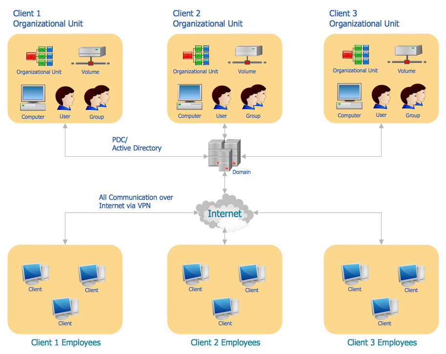
Example 1. Simple VPN Diagram
How does VPN Work?
VPNs allow to computers send and receive data through the public and shared networks as if they were directly connected to the private networks. Your data are routed through a VPN to the Internet, rather than directly through your ISP. VPN allows the geographically separated offices of one organization to connect securely forming one common network according to the projected VPN infrastructure diagram or schematic, and also offers the possibility for internet users to connect to proxy servers with protecting personal identity and location.
VPN uses tunneling protocols over networks and establishes a virtual point-to-point connection. The routing is realized through a private service, not the user's internet service provider. VPN hides an IP address and creates a private, encrypted tunnel through which a user accesses the Internet. It acts as a mediator between the user getting online and connecting to the Internet. VPN encrypts all your data and then passes them through a VPN tunnel, which others cannot access. A VPN tunnel diagram is useful to visually depict this mechanism.
VPN hides your IP address and redirects it through a specially configured remote server that is run by a VPN host. This VPN server becomes the source of your data and works like a filter that encrypts your data. In this way, when the user connects to the Internet using a VPN, all network traffic is sent through an encrypted secure connection via the VPN, and security and protection are ensured. Now, your internet provider and third parties cannot see which websites you visit, what data you send or receive, and cannot intercept them.
VPN provides a secure connection between two points communicating over a network, can combine several networks into a single network, and helps to extend access to a private network by providing remote authorized access to it. When a remote worker has authenticated to the private network, the encrypted channel is set up, and all traffic between this user and the corporation server flowing over the VPN is encrypted.
VPN also helps to bypass geographic internet restrictions or firewalls. It masks a user’s true location to the one set in the VPN and the user takes access to the websites and content allowed in that region.

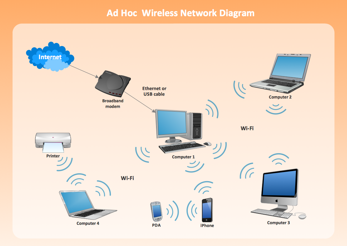
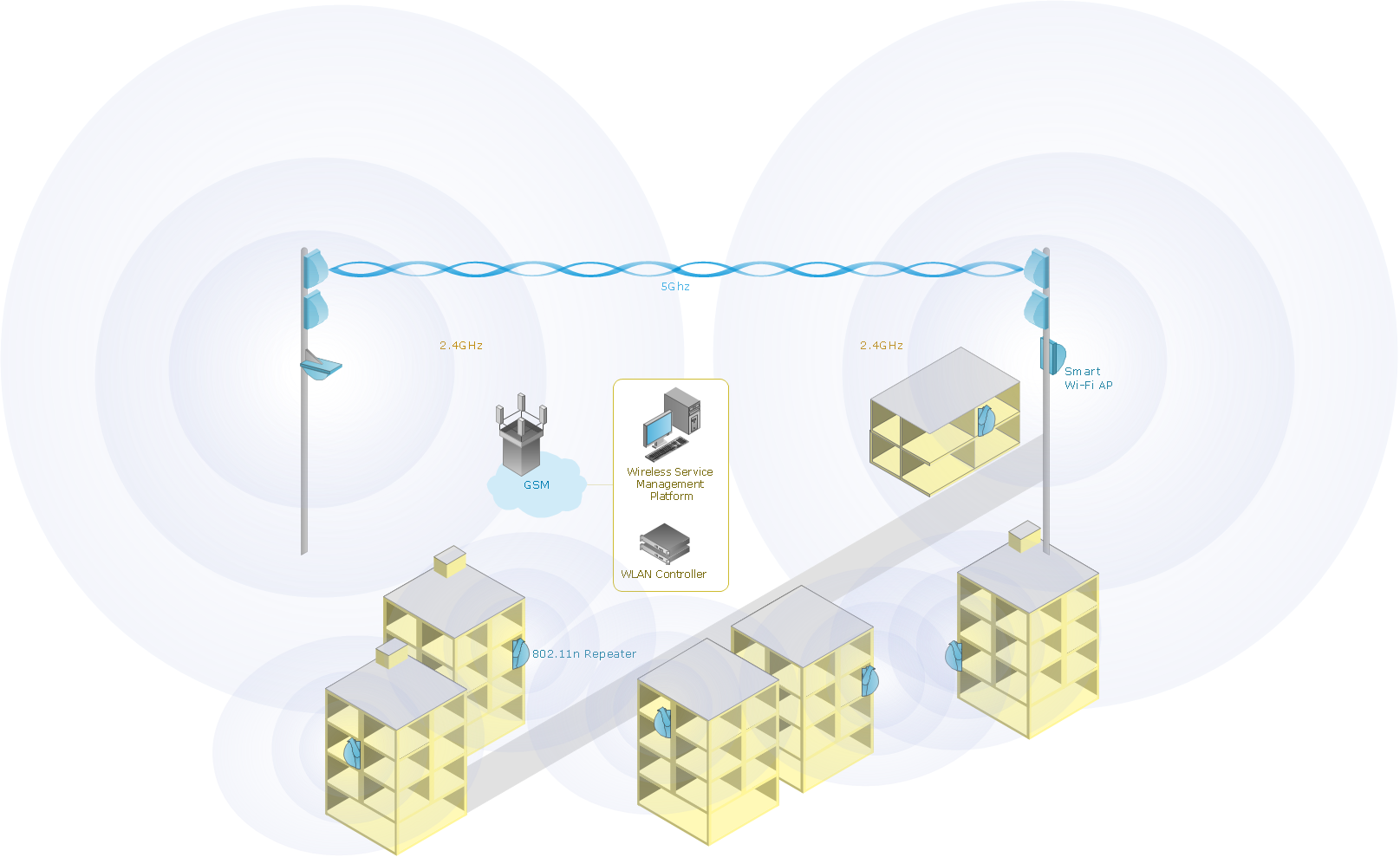
Example 2. VPN Network Diagram
Types of VPNs
There are four main types of VPNs:
- Personal VPNs
- Remote access VPNs
- Mobile VPNs
- Site-to-site VPNs
Personal VPNs enable individuals to establish secure and private connections to the open Internet. They hide your personal IP address from your internet service provider and also allow to bypass firewalls and geographic internet restrictions when access to some content is limited to specific regions. VPN encrypts your internet traffic and directs it through a remote VPN server. In this way, your IP address is concealed and anonymity and privacy are ensured. Personal VPN is especially valuable when connecting to public Wi-Fi networks, which in most cases are unencrypted and subject to access by malicious actors and hacker attacks.
Remote access VPNs provide remote access for the individual computers to a private network. It is the most popular type of VPN nowadays. For example, the company can make its own private network and the employees access it remotely and securely via a remote VPN when they work from home or any other place. In this way, workers access remotely company resources, files, applications, or the internal system, can work efficiently and collaborate with colleagues. It is also convenient for the company's IT support to troubleshoot devices, servers, and systems remotely. Remote access is realized through the creation of the encrypted tunnel between the user's device and private network after the authentication or verification of the identity, which is realized through individual credentials, in common, login and password.
Mobile VPNs allow you to connect to a local network from mobile devices, ensure the encrypted protection of data, and are useful in conditions of the absence consistent or stable internet connection. A mobile VPN is a virtual private network example that masks your IP address, keeps your data safe, ensures a permanent connection, and addresses spotty and variable Wi-Fi and mobile data performance. It maintains the same session and doesn't interrupt your apps, even when you switch from one internet connection to another, from Wi-Fi hotspot to mobile data. A mobile VPN helps to avoid buffering screens and interruptions and is incredibly useful for remote work providing quick access to data during business trips and traveling.
Site-to-site VPNs connect networks and enable organizations to combine several networks from different locations into a single network (intranet). These are own networks, for example, two offices of the same company, geographically remoted, or also networks of partner companies (extranet). The main goal is to provide access to resources for multiple users in various fixed locations. They are incredibly useful in large-scale business environments to ensure secure communication and sharing of information and resources between departments all over the world. These VPNs provide confidentiality by creating an encrypted tunnel and encrypting data to protect them from unauthorized access.
How to Create VPN Flowcharts?
Computer and Networks Area for ConceptDraw DIAGRAM software provides libraries with ready-to-use predesigned vector stencils to help you create the VPN network diagram or flowchart, and implement Virtual Private Networks quickly, easily, and effectively. VPN Flowchart gives an understanding of VPN configuration, its components, fundamental principles and basics of work, and common protocols. It is useful to depict all VPN hardware components and VPN architecture, which includes VPN tunnel, VPN management, and VPN configuration components.
Stop hackers and snoops from accessing your connection and online communication, protect your personal information, and keep data you send and receive anonymous and secure with a VPN. Design how VPN works diagram, show how it encrypts traffic and protects your data and activity from tracking by internet service providers, internet browsers, cable companies, and different websites by designing illustrative flowcharts and diagrams.
VPN Diagram Examples
Computer and Networks Area for ConceptDraw DIAGRAM provides a collection of professionally looking examples of Virtual Private Networks. All they are useful as examples and templates for your own VPN diagram, flowchart, and network prototypes. VPN is more than improving the built-in security layers of your devices. Explore all the benefits and disadvantages of VPNs and choose the best secure remote access solution for your company.

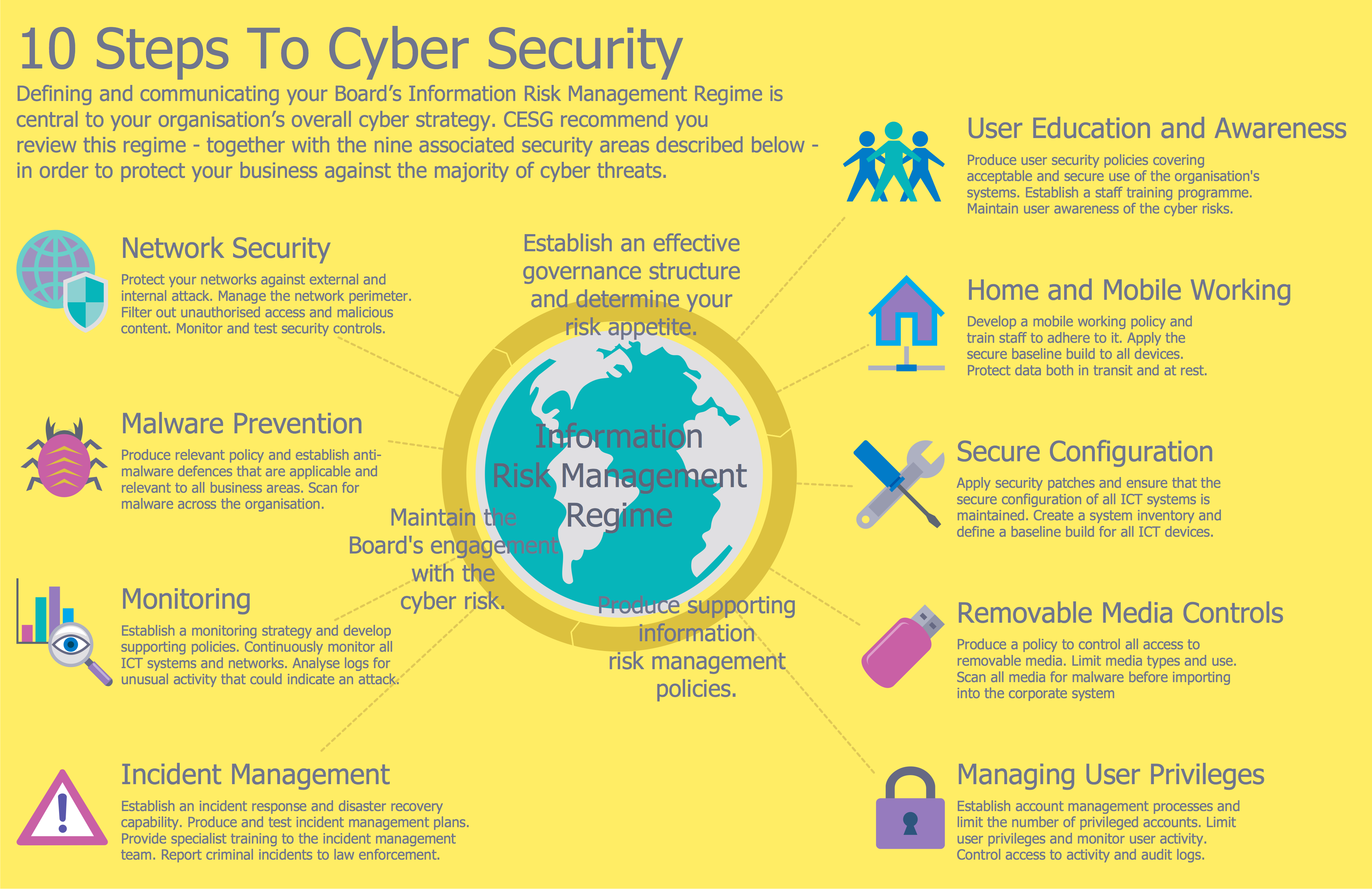
Example 3. Virtual Private Network Example
The examples you see on this page were created in ConceptDraw DIAGRAM using the Computer and Networks Area of ConceptDraw Solution Park and show the Virtual Private Network (VPN) diagrams.
The diagrams designed with ConceptDraw DIAGRAM are vector graphic documents and are available for reviewing, modifying, and converting to a variety of formats (image, HTML, PDF file, MS PowerPoint Presentation, Adobe Flash or MS Visio).