How To Create Onion Diagram
A diagram is known to be a symbolic representation of information using the visualization techniques. Diagrams are very widely used nowadays, becoming more popular since the “Age of Enlightenment”, also known as the “Age of Reason”, which was a philosophical as well as intellectual movement, dominated the world of ideas in Europe during the 18th century, thus called the “Century of Philosophy”.
Sometimes, the techniques mentioned above includes the usage of the 3-D visualization, also known as “three-dimensional” one. This type of visualization later gets projected onto a two-dimensional, or 2-D, surface. The word “graph” itself can be sometimes used instead of a word “diagram”, although the last one is still more commonly used, having a general as well as specific meaning: the “diagram” is used as a collective term standing for the whole class of technical genres, including technical drawings, tables and graphs. This term is a specific kind of a visual display, showing the qualitative data using different shapes, connected by the arrows, lines and other visual links.
In science, the term “diagram” is used in both ways: they are simply pictorial and abstract representations of some kind of information. The so well-known line graphs, maps, bar charts, architects’ sketches and engineering blueprints are all variations of diagrams. Some of them include images, photographs and videos, some of them – do not. Diagrams can also be described as the abstract graphic portrayals of the subject matter, which they represent. Diagrams, as well as charts, are known to be contrasting with technical illustrations, computer graphics, technical drawings and infographics in a way of showing more abstract, not as many literal representations of information. The essence of a diagram can be seen as a display, which does not show any numerical data, but more the abstract information, as well as the relationship. They can be also treated as a form of visual so-called “formatting” devices. The diagrams may be found being the ones with the building blocks, such as the geometrical shapes connected by arrows, lines and other visual links.
Diagrams can be also defined as simplified figures, based on a set of particular rules. There are very many kinds of diagrams, including the one, known as an “onion diagram”. This kind of diagram is basically a chart that shows the connections as well as the relationships of each of the parts of some organization with another one. With the help of such “onion diagrams” it is also simpler to illustrate the way how one particular part of some process, or an organization itself, is depended on another part of the same process or same organization. The chart in a way of a diagram displays the items in the concentric circles.
The “Onion Diagram” is so well known and widely used for it being able to show all of the layers of the particular complete system in a way of a few circles, each of which is able to represent a component, that is dependent upon the component on the inside. This component is usually shown in a way of a circle inside another one. The main concept of such onion diagram is shown by the very centre circle of this diagram. The chart is used due to the fact that it has a clear visual representation, being easy to read, having a strong visual impact.
One of the types of the “Onion diagram” is so-called “Cultural Onion”. This “Onion” has all seven layers, including behaviors, artifacts, feelings, beliefs, values, allegiance and worldview, which organize some person's life. The outer most layers are the most accessible. At the same time the in-depth ones are only accessible with the use of the connections to this particular person. The seven layers are integrated into three structural levels, known as the “foundational”, the “evaluating” and the “actualizing” ones. In order to create any needed “Onion Diagram”, including the “Cultural Onion” one, you can always use one of the best applications for doing it, which is ConceptDraw DIAGRAM software. Having this ConceptDraw DIAGRAM diagramming and vector drawing software extended with “Stakeholder Onion Diagrams Solution” is a benefit for you. The needed solution can be found as well as downloaded from the “Management Area” of “ConceptDraw Solution Park” and also from ConceptDraw STORE, which is another product of CS Odessa, developed for a reason of providing the solutions, simplifying the users work of making the diagrams and other charts.
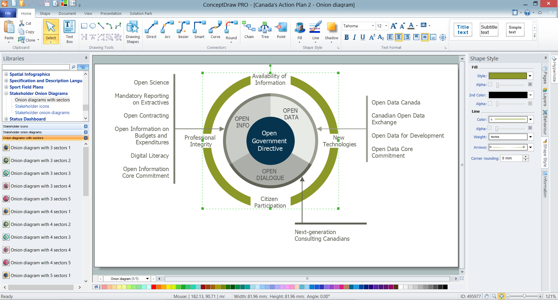
Example 1. How to create Onion Diagram
Using the Stakeholder Onion Diagrams Solution means getting the final great looking result as a smart “Onion diagram” much sooner. For this purpose, you can run ConceptDraw DIAGRAM and create your new document. After, you shall double-click on the needed object's icon, which you can find from the library included to the “Stakeholder Onion Diagrams solution” in order to place it in the very centre of your document while working in ConceptDraw DIAGRAM software. To make the changes you shall simply click on the diagram segment in order to select it, so after you will be able to change its position, as well as its size or even to remove it, once it is urgently needed.
To type the text on your diagram you can simply select any of the needed segments and to type there your information. You can also drag the control dots to regulate the text positions. Do not forget to use Fill, Line, Text and Shadow tools in order to format your diagram.


Colourful stakeholder icons as well as stakeholder onion diagrams vector objects are all represented by three different libraries included to “Stakeholder Onion Diagrams solution”. Thanks to them the ConceptDraw software can guarantee you a fun and entertaining process of creating the diagrams as well as a great looking as well as a professionally looking result.


Another way of drawing any needed “Onion Diagram” using ConceptDraw DIAGRAM software is to use the pre-designed template or the existing sample from the ConceptDraw STORE as the base for your own diagram. The whole collection of templates and samples is always available for ConceptDraw DIAGRAM users.

Example 2. New Zealand Public Sector Agencies Onion Diagram
The samples you see on this page were created in ConceptDraw DIAGRAM software on the base of predesigned templates from the Stakeholder Onion Diagrams Solution and successfully show how to create Onion Diagram in ConceptDraw DIAGRAM An experienced user spent 10 minutes creating each of them.
Use the Stakeholder Onion Diagrams Solution for ConceptDraw DIAGRAM software for fast, easy and effective creation your own professional looking Onion Diagrams of any complexity.
All source documents are vector graphic documents. They are available for reviewing, modifying, or converting to a variety of formats (PDF file, MS PowerPoint, MS Visio, and many other graphic formats) from the ConceptDraw STORE. The Stakeholder Onion Diagrams Solution is available for all ConceptDraw DIAGRAM users.