Scrum is a popular iterative and incremental agile framework for managing product and software development. For planning a project, tracking the defects, bugs, work and blocking issues when developing software, viewing and reporting a progress, the teams working with Scrum methodology use the product backlog items (PBIs), bug work item types (WITs), reports and dashboards. When defining a product backlog item, you can focus on the value which will be received by your customers without description how this will be achieved. Working in sprints, the teams can define tasks which automatically link to PBIs and bugs.
ConceptDraw DIAGRAM diagramming and vector drawing software extended with SCRUM Workflow solution from the Project Management area of ConceptDraw Solution Park offers collection of samples, variety of predesigned objects, clipart and graphic elements, a set of Scrum process work items and workflow which are developed for agile teams working using Scrum.
SCRUM Workflow Solution was specially designed to give you the opportunity to create Scrum diagrams and charts, visualize scrum processes and scrum workflow without efforts. Simply create new document and drag the needed objects from the libraries of SCRUM Workflow Solution to make your own professional looking and successful diagram or infographic.
8 libraries of the SCRUM Workflow Solution contain 276 objects, all they are vector and ready-to-use.
Pay special attention for the Scrum Charts library which offers 4 live objects:
Release burndown chart - lets conviently track the progress on a Scrum project.
Release velocity chart - helps to determine how many points worth of work can be completed per sprint for a given team.
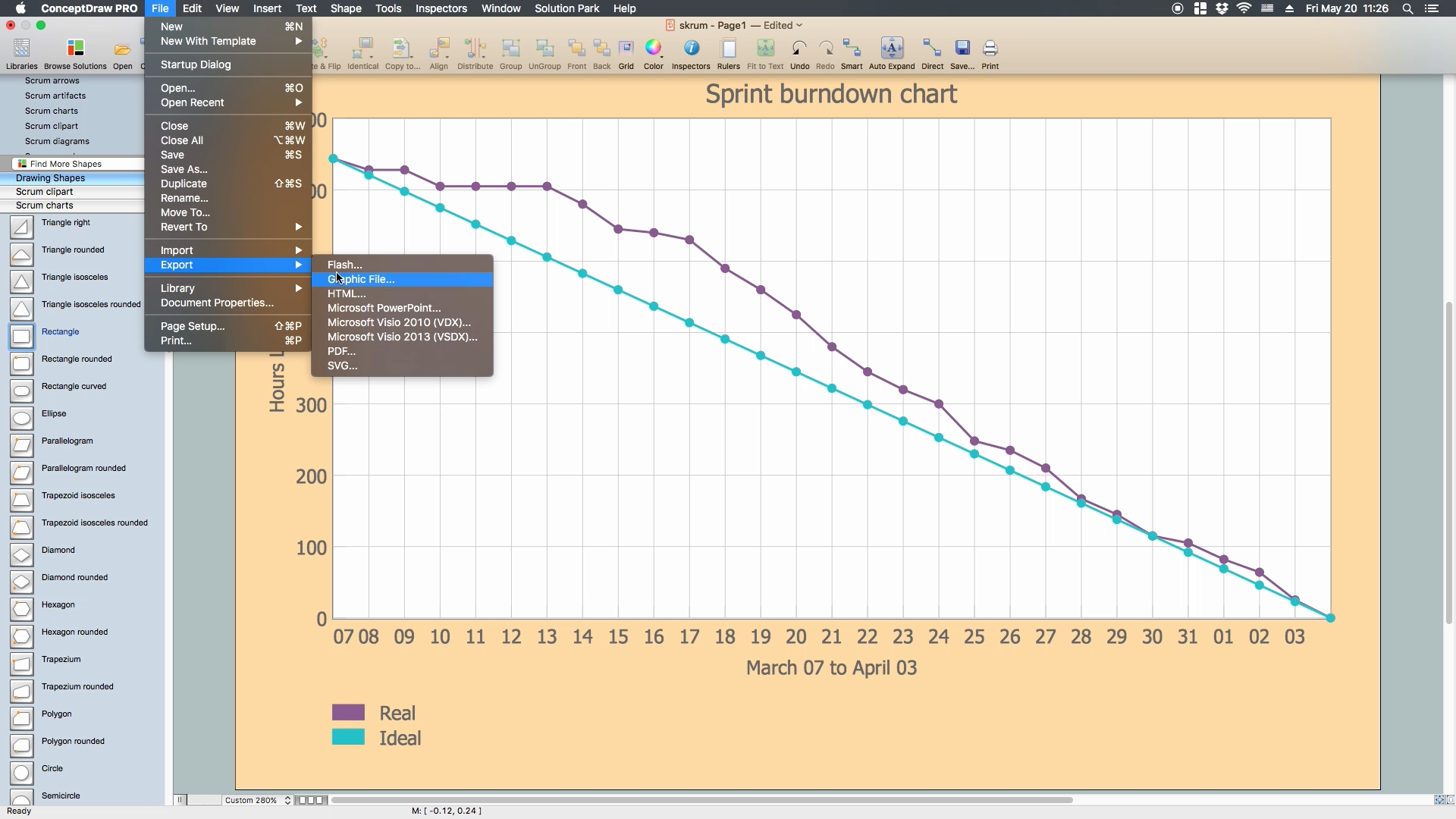
Sprint burndown chart - is used to track the product development effort remaining in a sprint.
Team velocity chart - depicts the effort for a specific team against multiple sprints and multiple releases to compare team capacity against performance.
How to Create a Burndown Chart
Using the predesigned Scrum charts objects you can create your own chart in minutes - drag desired object from the library to your document, simply enter the values and they will be reflected instantly on the chart.
Start a new document.
Set a page orientation via File menu - Page Setup.
From a Scrum charts library take a Sprint burndown chart object
Enlarge the graph using sharp handle.
Rename table columns headings.
Related names on the graph will change automatically.
Use object action menu.
Set the needed quantity of points for the graph.
For this case it is equal to the quantity of days from March 3rd to April 7th.
For handful usage, move the table to a free space on the page.
To do so, use a yellow control dot.
Fill a table with data.
To select a cell, click a few times on it.
Use object action menu.
Set the increment for Y axis.
Use object action menu.
Set the maximum value for Y axis.
That value can't be less than a maximum number indicated in the table.
Select a cell Real, select a Color menu.
Set a color for the header cell.
The color of the line graph and legend data will update automatically, as these parameters are connected.
Use object action menu.
Hide the table with data, you don't need it anymore.
Stretch the graph adjusting it to the page size.
Move the legend under the graph using a yellow control dot.
Use layers inspector.
Rename the second layer and set it as active.
Lock the previous layer for editing.
Use a rectangle from Drawing Shapes library.
Stretch it out to the page size.
Change the color.
Open Fill color menu of Fill inspector.
Uncheck the stroke for perimeter rectangle.
Send it to Back using context menu.
Open Layers inspector.
Set the first layer as active.
Lock the background layer for editing.
If transparent graph lines dissapeared on the background, use a rectangle again.
Set the needed size, select the graph by clicking on its components.
Send the graph to Front.
Select the graph object.
Open line inspector.
Set the line pattern to a solid one.
Your document is ready!
Save it and export to another format if needed.
The possibility of exporting to variety of popular graphical formats (PNG, JPEG, JPG, GIF, TIF, TIFF, BMP, DIB, EMF, SVG) and file formats, such as Microsoft PowerPoint (PPT), Adobe Acrobat (PDF), Microsoft Visio (VDX, VSDX), Adobe Flash (SWF), Encapsulated PostScript (EPS), HTML, opens wide opportunities for you.
Video. How to Create a Burndown Chart (1min 08sec)
Use the tools of the SCRUM Workflow Solution for ConceptDraw DIAGRAM to create your own professional looking Scrum diagrams, represent scrum process work items and workflow fast, easy and effective.
Data modeling is actively applied in analysis and uses wide set of methods for description the data requirements in a system. One of the most popular and well-known is the ERD method of database modeling.
The best ERD tool for the Mac and Windows is ConceptDraw DIAGRAM software extended with the Entity-Relationship Diagram (ERD) solution from the Software Development Area for ConceptDraw Solution Park, which is sharpened for professional ERD drawing and data modeling with Entity Relationship Diagram.
Picture: Data Modeling with Entity Relationship Diagram
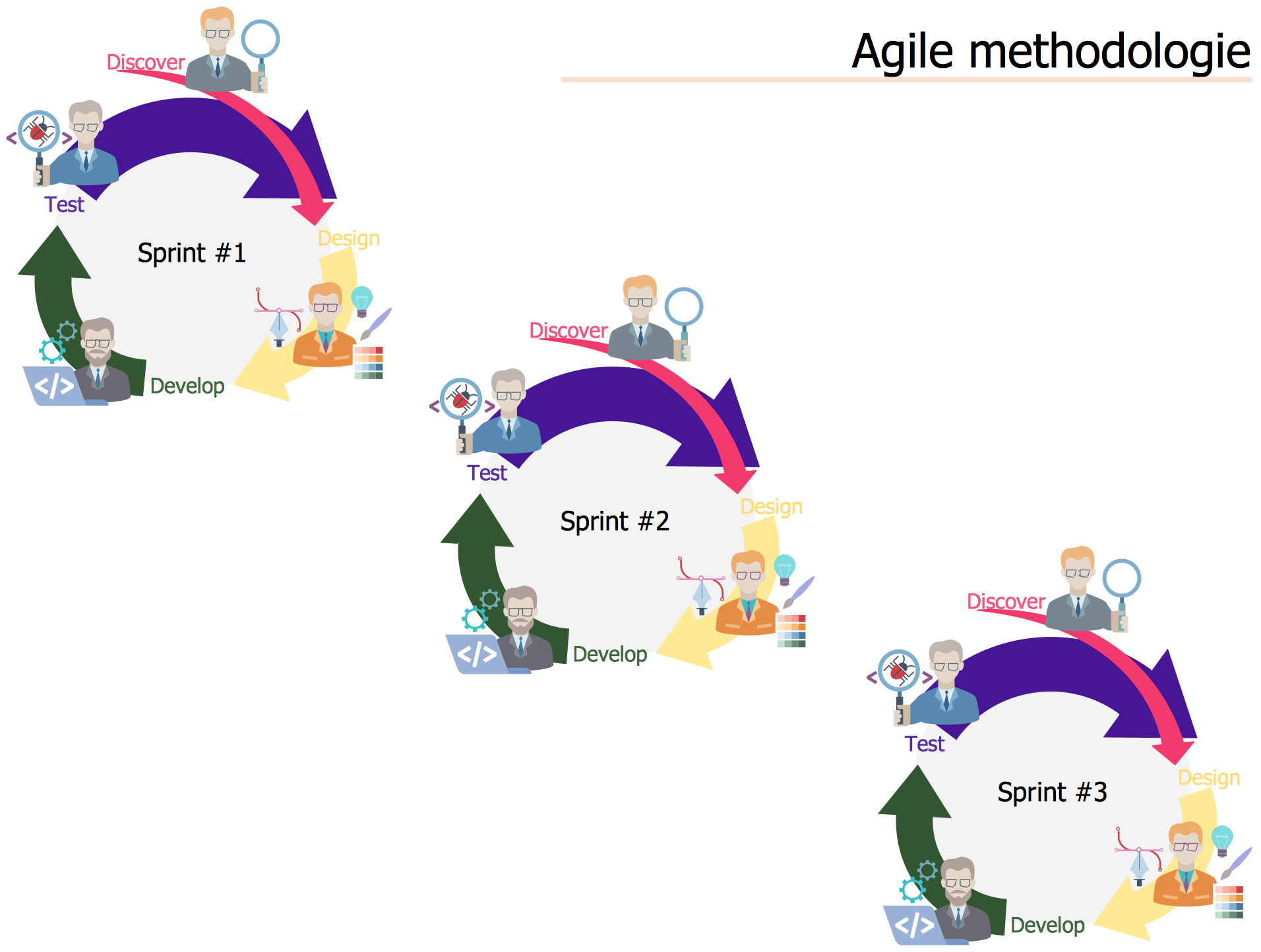
Agile methodology is an excellent alternative to waterfall and traditional sequential development. ConceptDraw DIAGRAM software extended with SCRUM Workflow solution is ideal for quick and easy designing various diagrams, charts, mind maps and schematics illustrating software development using Agile methodologies, and in particular Scrum methodology.
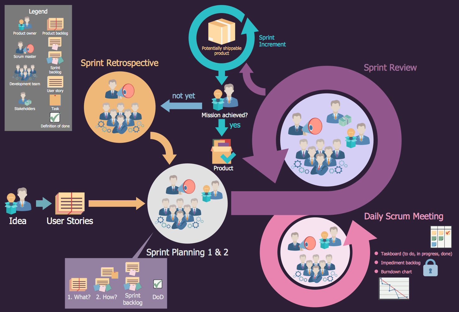
What is Scrum? Scrum is the famous agile software development methodology which depicts an iterative and incremental approach for the work on the complex projects. Use ConceptDraw DIAGRAM diagramming and vector drawing software extended with SCRUM Workflow solution to draw various types of professional-looking Scrum Charts, Scrum Workflow Diagrams, Scrum Mind Maps, Scrum boards and attractive Scrum Infographics.
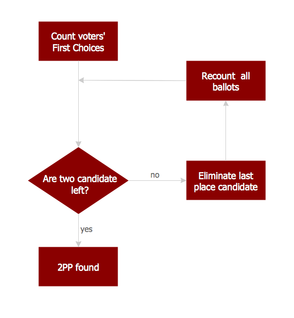
A flowchart is a simple but very functional tool when it comes to understanding a workflow or to removing unnecessary stages from a process. When drawing flowcharts, keep in mind that there are four common types of flowcharts, like document flowcharts and data flowcharts that show control over a data or document flow over a system. To show controls on a physical level, use system flowcharts. In addition, to show controls in a program, you can draw a program flowchart.
This flowchart diagram represents the piece of an article editing process, that involves the author and editor. It was created using the Basic Flowchart notation that consists from the basic flowchart symbols. The start and the end of the process are indicated with "Terminator" symbols. The "Process" symbols show the action steps consisting from making edits and searching for a compromise, when the author does not agree with the suggestions of the editor. The "Process" symbol is the general symbol in process flowcharts. The "Decision" symbol indicates a branching in the process flow. There are two branches indicated by a Decision shape in the current flowchart (Yes/No, Disagree/Agree). This basic flowchart can be used as a repeating unit in the workflow diagram describing the working process of some editorial office.
This sample was created in ConceptDraw DIAGRAM diagramming and vector drawing software using the Flowcharts solution from the Diagrams area of ConceptDraw Solution Park.
This sample shows the Flowchart that displays the procedures of 2PP (two-party preferred) voting and counting the voters. The two-party-preferred vote is the result of the elections that was distributed to the final two parties.
There are many tools to manage a process or to illustrate an algorithm or a workflow. Flowcharting is one of those tools. However, it may be difficult to show complex processes that require multiple attributes or several people in a simple flowchart, so a cross-functional flowchart would be a solution for that situation. To create such flowchart, group processes and steps to labeled rows or columns, and divide those groups with horizontal or vertical parallel lines. It is worth mentioning that there are different types of cross-functional flowcharts, like opportunity or deployment flowchart.
This diagram shows a cross-functional flowchart that was made for a trading process. It contains 14 processes, distributed through 5 lines depicting the participants who interact with the process. Also there are connectors that show the data flow of information between processes. The cross-functional flowchart displays a detailed model of the trading process, as well as all participants in the process and how they interact with each other. The lines in the flowchart indicates the position, department and role of the trading process participants.
A database is a data collection, structured into some conceptual model. Two most common approaches of developing data models are UML diagrams and ER-model diagrams. There are several notations of entity-relationship diagram symbols and their meaning is slightly different. Crow’s Foot notation is quite descriptive and easy to understand, meanwhile, the Chen notation is great for conceptual modeling.
An entity relationship diagrams look very simple to a flowcharts. The main difference is the symbols provided by specific ERD notations. There are several models applied in entity-relationship diagrams: conceptual, logical and physical. Creating an entity relationship diagram requires using a specific notation. There are five main components of common ERD notations: Entities, Actions, Attributes, Cardinality and Connections. The two of notations most widely used for creating ERD are Chen notation and Crow foot notation. By the way, the Crow foot notation originates from the Chen notation - it is an adapted version of the Chen notation.
This sample shows the UML Class Diagram that was created in ConceptDraw DIAGRAM on the Mac and then was opened for editing in MS Visio.
Using the 13 libraries of the Rapid UML Solution for ConceptDraw DIAGRAM you can create your own visual vector UML diagrams quick and easy.
Use ConceptDraw DIAGRAM software with Flowcharts Solution to create Process Flow Charts, Flow Chart Process Maps, and High-Level Process Flow Charts to illustrate ✔️ high-level processes in industrial, chemical, and process engineering, ✔️ major plant processes, ✔️ minor details
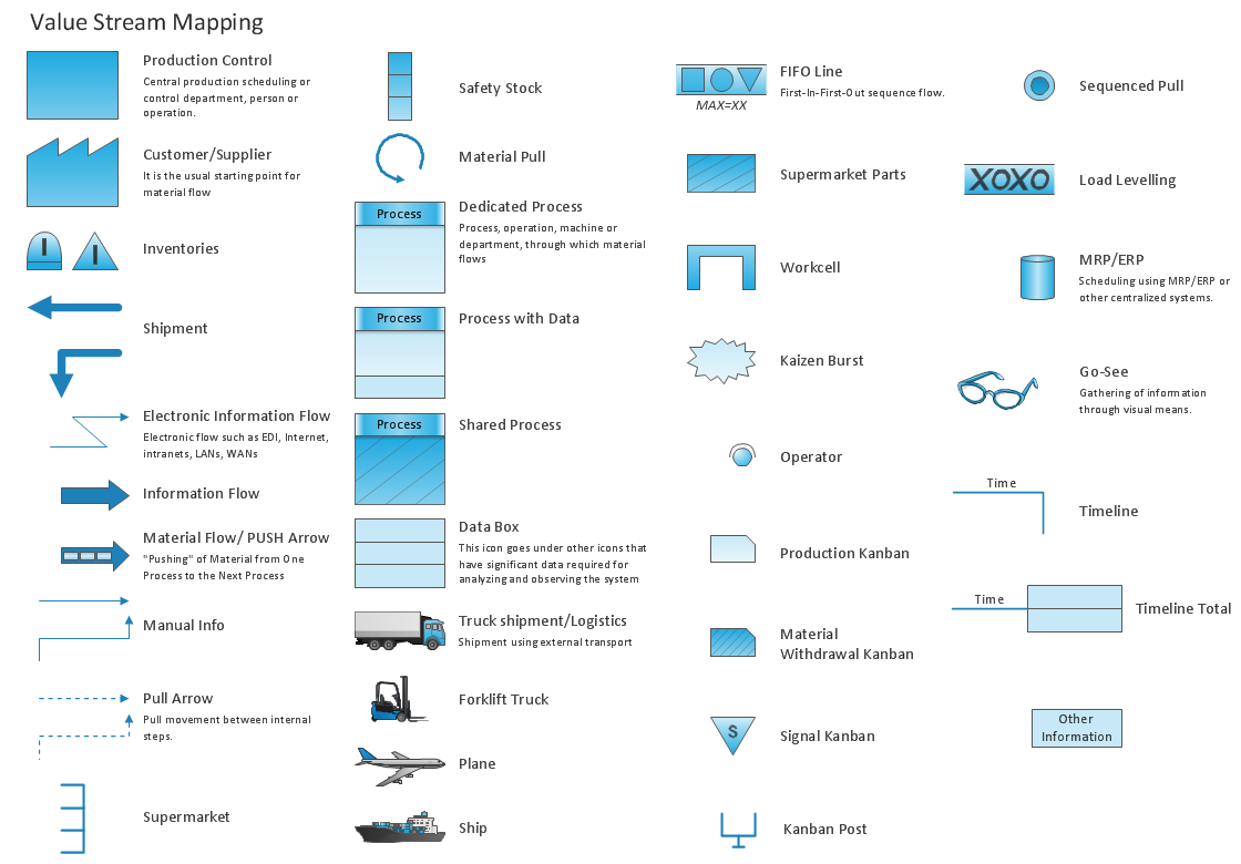
The Value Stream Mapping solution continues to extend the range of ConceptDraw DIAGRAM into a business graphics tool that can be used to document processes of Lean Manufacturing.
 Scrum Arrows Library
 Scrum Artifacts Library