How to Create a Column Chart
Vertical bar chart, 3D bar chart and Cylindrical bar chart shapes.
- Drag and drop bar chart shape from the library to your document.
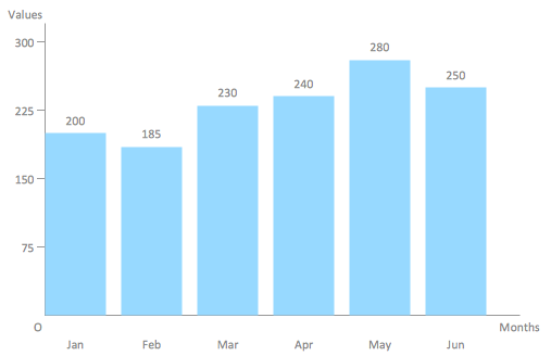
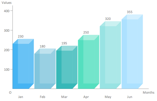
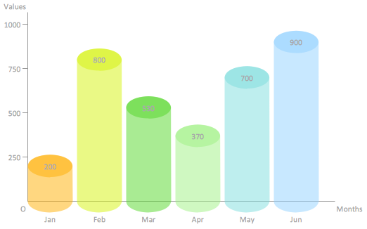
- Select the bar chart by mouse click. The Action menu icon appears.
- Click on the icon to open Action menu.
- To change bar number use Action menu commands Add bar, Remove bar, Set bar number.
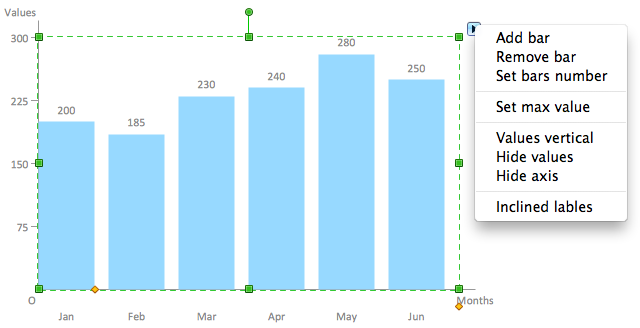
- To set maximum value for vertical axis use Action menu command Set max value.
- To change orientation of bar labels use Action menu command Values vertical/horizontal.
- To hide or show values over the bars use Action menu command Hide/Show values.
- To hide or show axises use Action menu command Hide/Show axis.
- To change value in a bar select chart, then select bar and type new value.
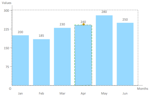
- To add or change chart caption select bar chart and simply start typing.
- To change orientation of category labels under horizontal axis use Action menu command Inclined/Horizontal labels.
- To move category labels up and down select the bar chart and use control dot in the bottom right corner of the shape.
- To change bar width and space between bars select the bar chart and use control dot on the horizontal axis.
Double bar chart shape.
- Drag and drop bar chart shape from the library to your document.
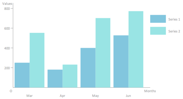
- Select the bar chart by mouse click. The Action menu icon appears.
- Click on the triangle icon to open Action menu.
- To change bar number use Action menu commands Add bar, Remove bar, Set bar number.
- To set maximum value for vertical axis use Action menu command Set max value.
- To change orientation of bar labels use Action menu command Values vertical/horizontal.
- To hide or show values over the bars use Action menu command Hide/Show values.
- To hide or show axises use Action menu command Hide/Show axis.
- To change value in a bar select chart, then select bar and type new value.
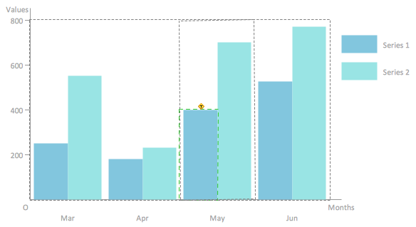
- To add or change chart caption select bar chart and simply start typing.
- To change orientation of category labels under horizontal axis use Action menu command Inclined/Horizontal labels.
- To move category labels up and down select the bar chart and use control dot in the bottom right corner of the shape.
- To change bar width and space between bars select the bar chart and use control dot on the horizontal axis.
- To set category names select the bar chart, then select legend, and then select a category and start typing.
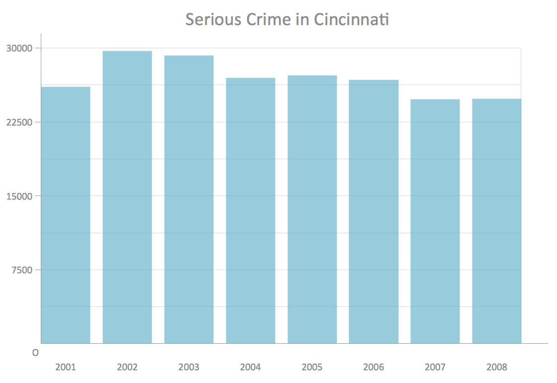
Example 1. Column chart example - Serious crime in Cincinnati.
See Also:
- How to Create a Bar Chart
- How to Create a Line Chart
- How to Create a Pie Chart
- How to Create a Pyramid Chart
- How to Create a Scatter Chart
TEN RELATED HOW TO's:
ConceptDraw Pyramid Diagram software allows drawing column charts using predesigned objects or drawing tools.
Picture: Pyramid Diagram
Related Solutions:
Problem Solving - ConceptDraw OFFICT suite is a software for the problem solving. The Seven Management and Planning Tools solution is a set of such tools for investigating complex problems.
These tools are exemplary at organizing research, parsing complex problems, providing a structure for the details, helping managers make decisions, and organizing effective communications in a visual manner that keeps everyone involved.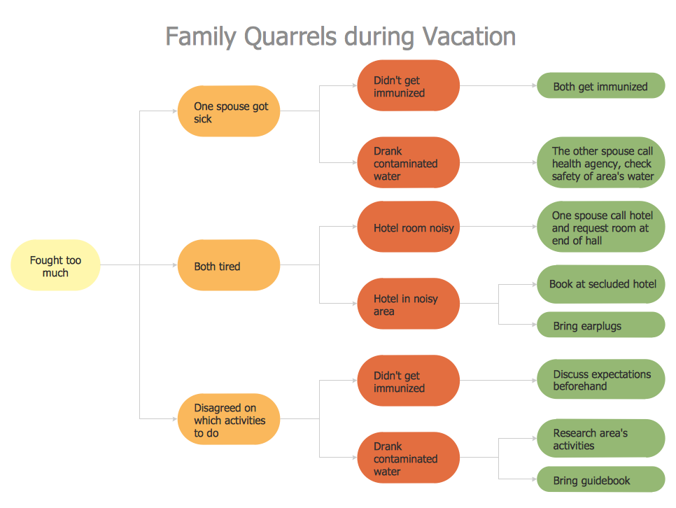
Picture: Problem solving
If you are an advanced diagramming software user, you might use it daily. Traversing the Internet in searching of alternative to MS Visio for MAC and PC, you can fulfill all your requirements with ConceptDraw DIAGRAM. Don’t hesitate to transfer your documents to another operating system.
When looking for a smart and simple tool for business diagrams as alternative to MS Visio for Apple OS X platform, ConceptDraw DIAGRAM certainly is the best choice. Making many kinds of business charts, numerous technical drawings is what ConcepDraw DIAGRAM is the best. One can easy create any diagram and complete it perfectly and quickly. The big collection of vector object libraries, templates and samples, make it the best Microsoft Visio alternative: ConceptDraw DIAGRAM is simpler to use, less expensive, and supports project management and mind mapping methods.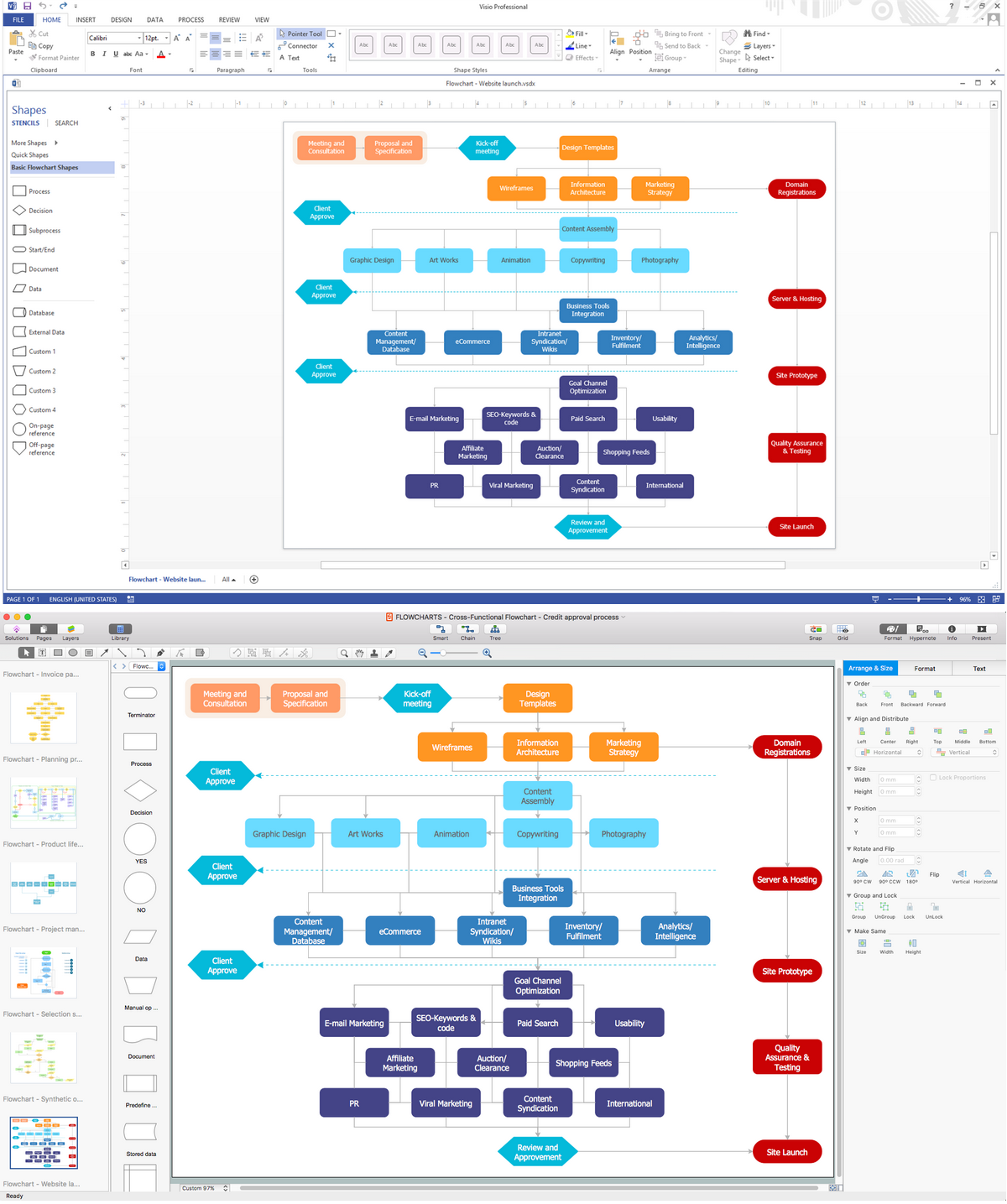
Picture:
In Searching of Alternative to MS Visio for Mac and PC
with ConceptDraw DIAGRAM
Use the advantages of hierarchical tree structure of mind map while developing the organizational structure of your organization. Create an Organizational Chart from your map. Double click the icon to create an Organizational Chart.
The diagram is created automatically from the active page of your map by ConceptDraw DIAGRAM and will be opened in Slideshow mode.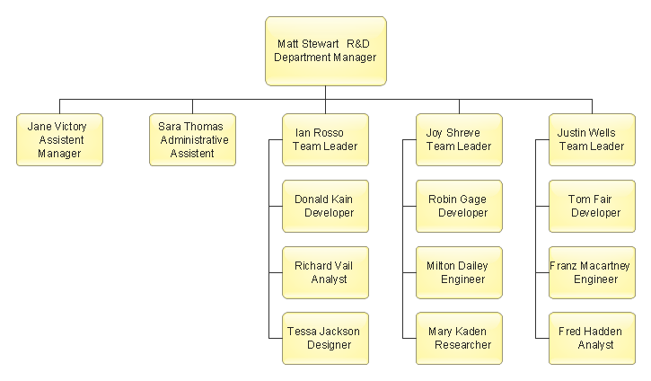
Picture: Organizational Chart
Related Solution:
No security system cannot be constructed without detailed security plan, or even a set of plans in some cases. ConceptDraw DIAGRAM software offers the Security and Access Plans Solution from the Building Plans Area to help you design the Security Plans for any premises and of any complexity.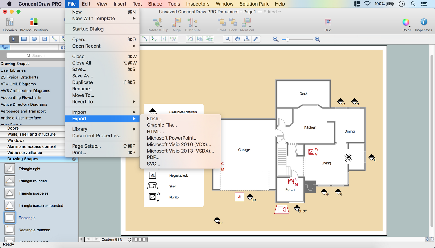
Picture: Security Plans
Related Solution:
Explore practical flowchart examples including business process diagrams, workflow charts, swimlane flowcharts, and IT troubleshooting flows. Review common patterns and start from ready templates.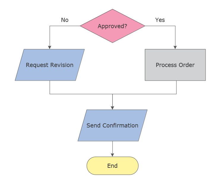
Picture: Flowchart Examples
Related Solution:
A triangular graphic representing Graham's hierarchy of disagreement, based on Paul Graham's March 2008 essay How to Disagree.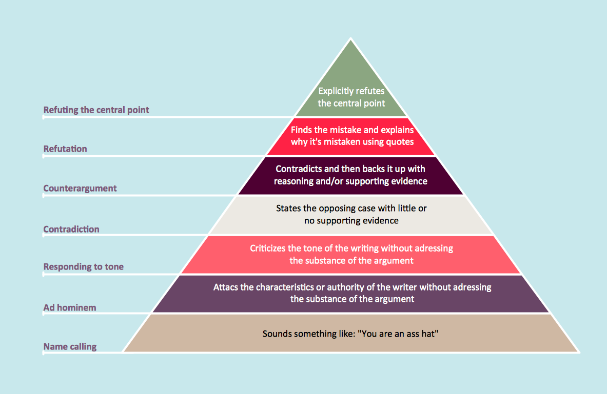
Picture: Pyramid Diagram
Related Solutions:
A process flowchart is a picture of the separate steps of a process in sequential order.Use ConceptDraw DIAGRAM software and the vector stencils from object libraries are designed objects you can use adding to process flowcharts for the best result.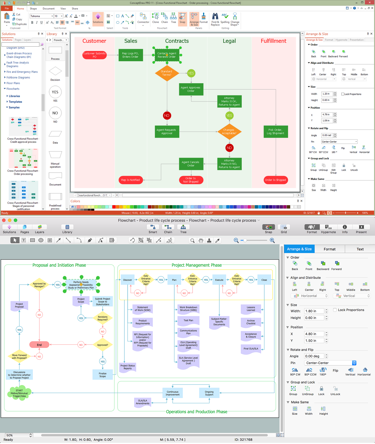
Picture: Create Process Flowcharts
Related Solution:
An orgchart shows how the responsibilities are divided between departments. It’s enough to have just one look on a proper organizational chart template to understand the idea and how it works. To understand how it’s made you should use a diagramming software.
This organizational diagram illustrates the possibilities of using ConceptDraw DIAGRAM to create orgcharts. This sample represents the common project management company. The chart shows the structure of devisions in the company, and the interaction between them. Communication between departments imply a certain structure affiliation and reporting. At the head of the company - President. This diagram was created using ConceptDraw solution for designing Organizational charts of any structure and complexity.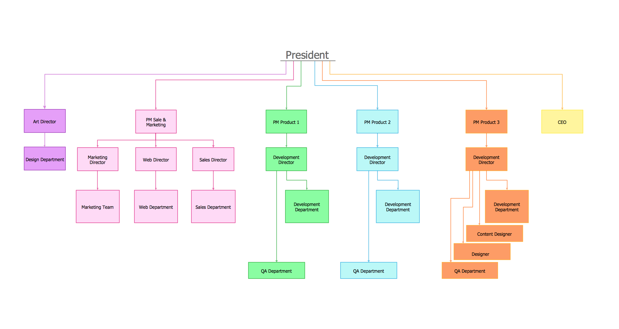
Picture: Organizational Chart Template
Related Solution:
Bureaucratic companies usually are characterized by a strict hierarchy and clearly defined responsibilities. However, sometimes organizational structure of a company reminds of somewhat tangled. To clarify it, you can create an orgchart that will represent the company as a tree with its' departments as branches.
This organization diagram represents a tree-like organizational structure. This is a typical example of a top-level branches of the hierarchical organizational structure. This part of the tree shows heads of branches who are subordinated completely to the president. The information and solutions are distributed though a tree structure down to the company's departments. Each of the sub-division has its own structure that is reflected in the corresponding organizational chart. This orgchart diagram was created using the vector graphic library supplied with ConceptDraw Organizational Charts solution.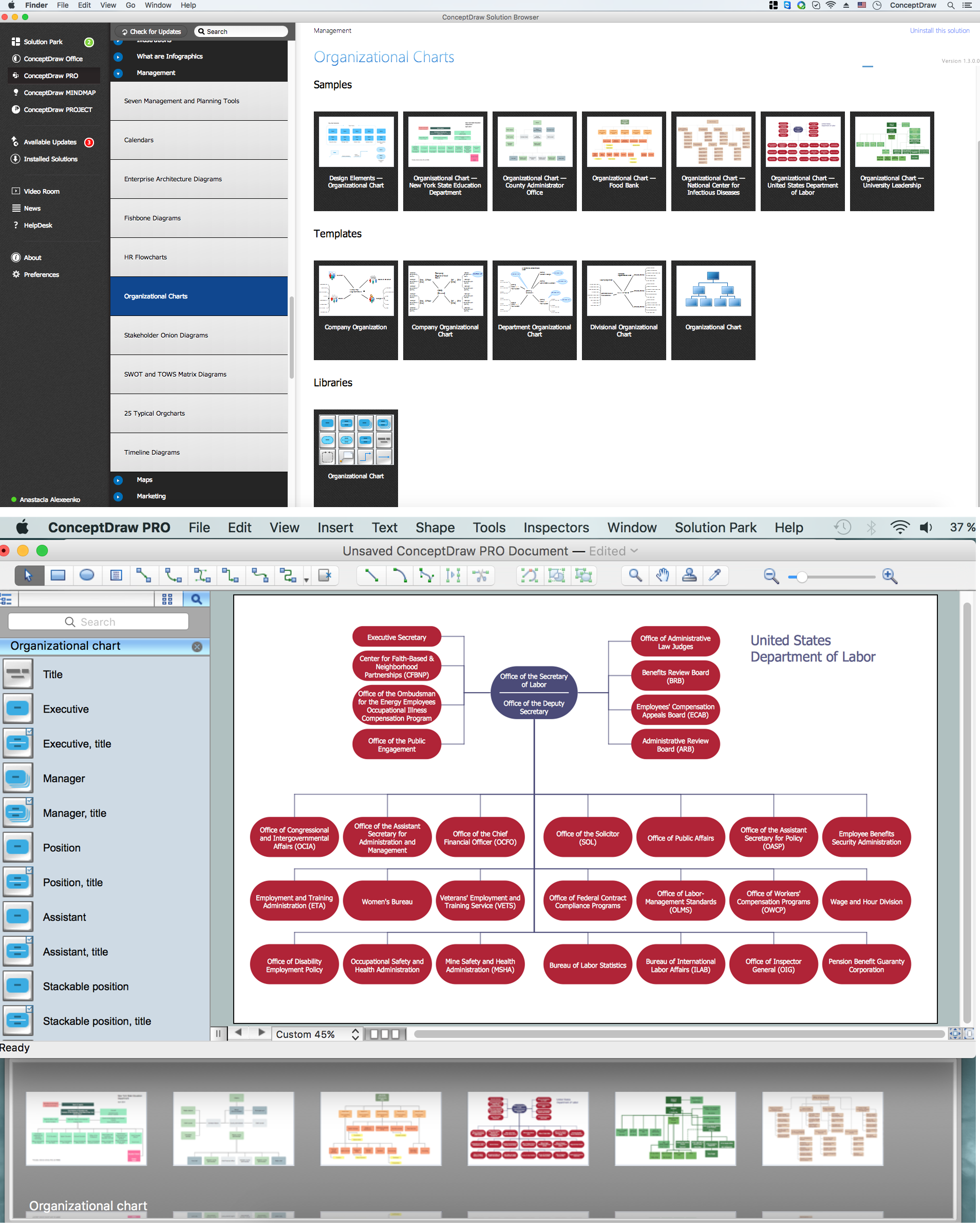
Picture: Organizational Structure
Related Solution:
ConceptDraw
DIAGRAM 18