ATM Solutions
UML Use Case Diagram Example. Services UML Diagram. ATM system

Account Flowchart Stockbridge System. Flowchart Examples

Accounting Flowchart Purchasing Receiving Payable and Payment
Work Flow Chart

HelpDesk
How to Create a Bank ATM Use Case Diagram

Yourdon and Coad Diagram

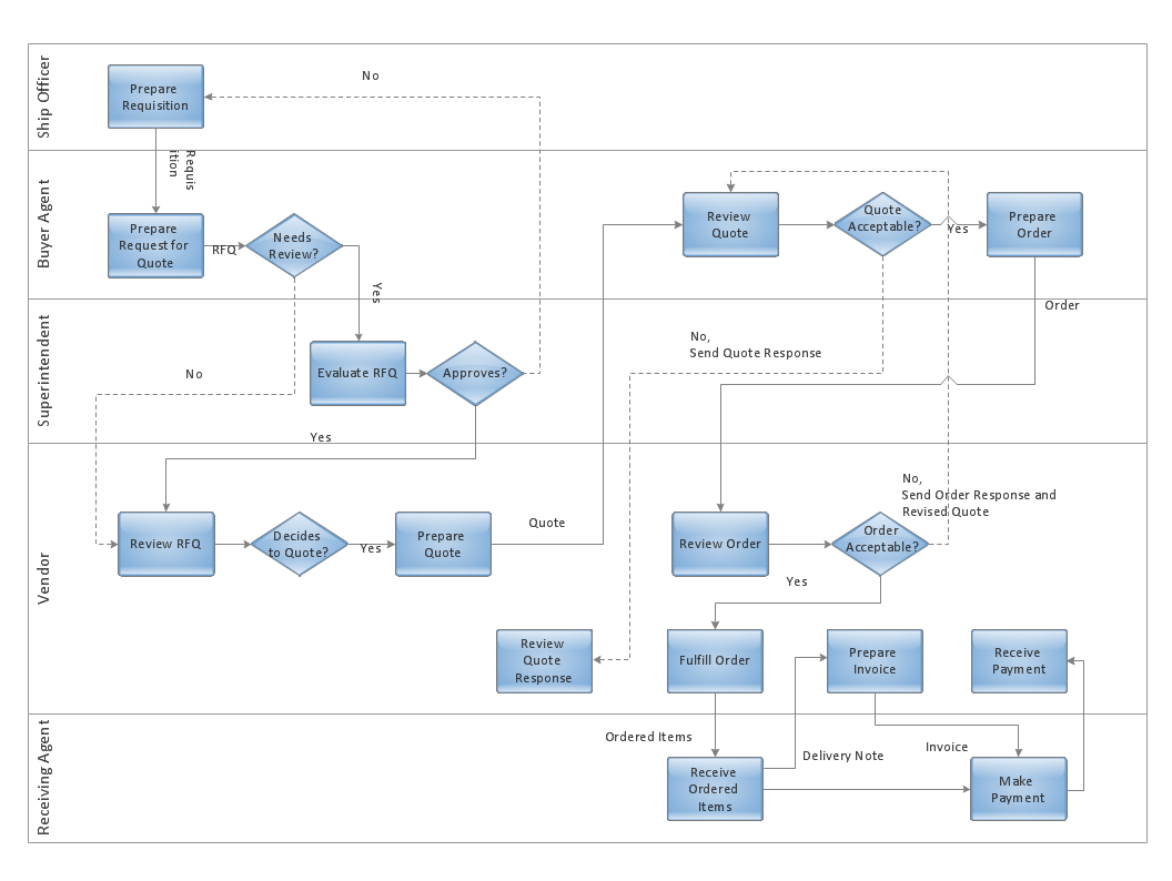
 Cross-Functional Flowcharts
Cross-functional flowcharts are powerful and useful tool for visualizing and analyzing complex business processes which requires involvement of multiple people, teams or even departments. They let clearly represent a sequence of the process steps, the order of operations, relationships between processes and responsible functional units (such as departments or positions).
Formalization and Verification of Event-driven Process chain
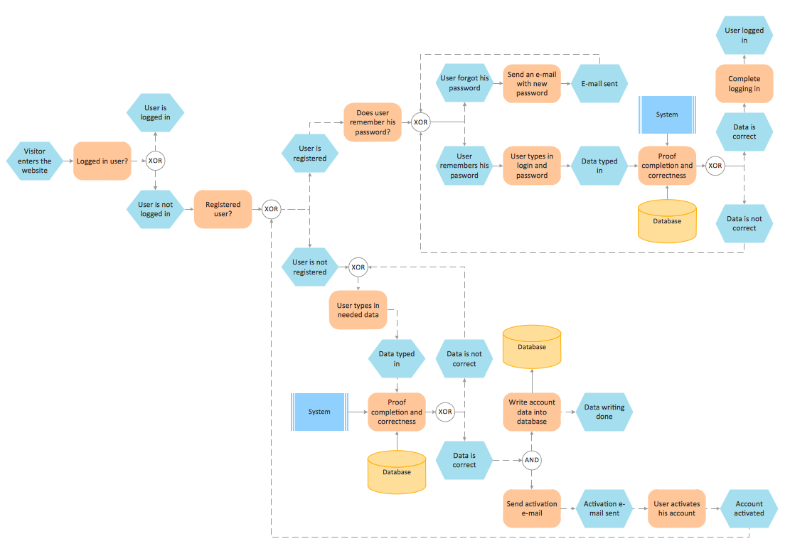
UML Activity Diagram

Cross-Functional Flowcharts in ConceptDraw
UML Sequence Diagram


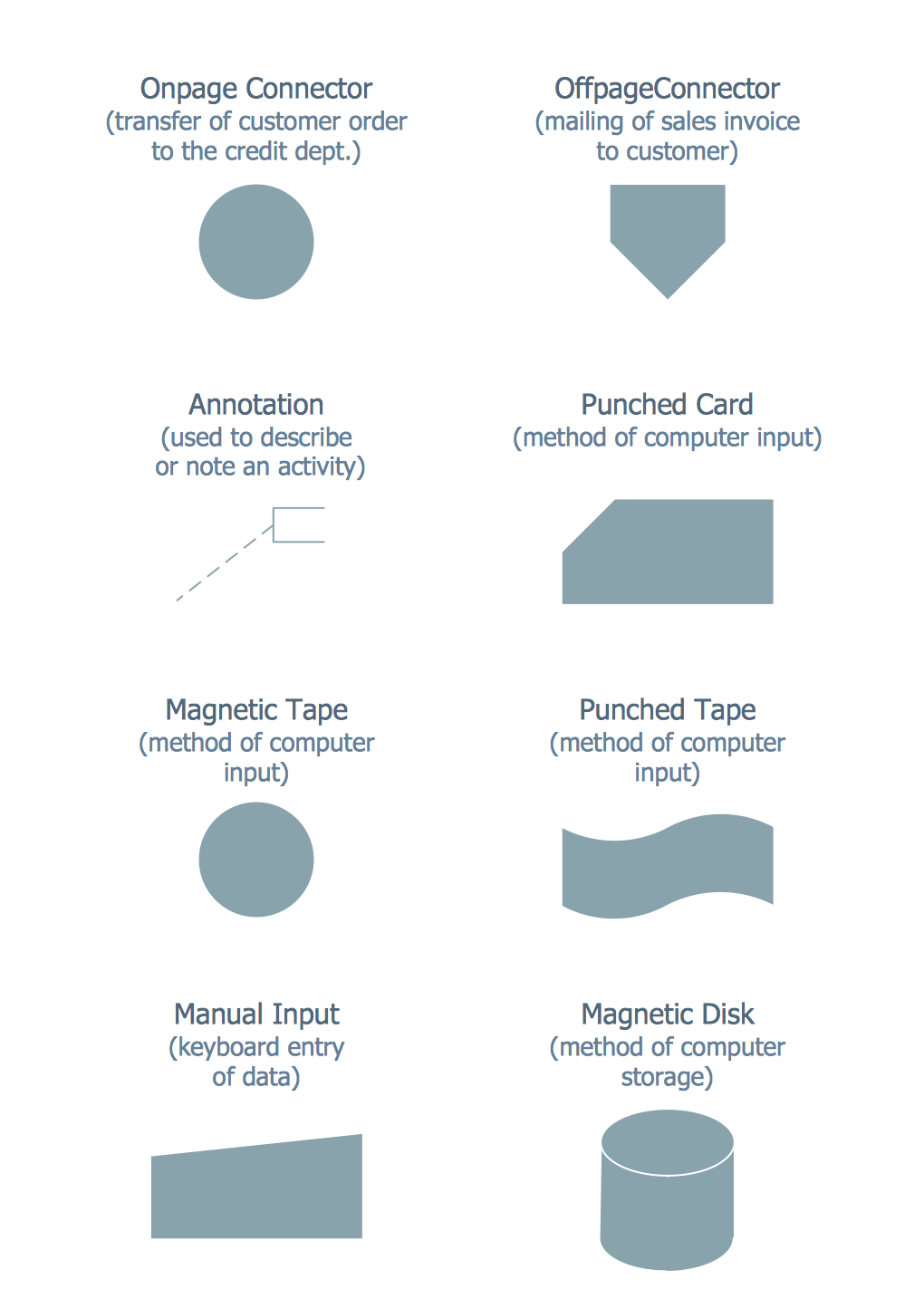
IDEF0 Flowchart Symbols

Design Elements for UML Diagrams

UML Collaboration Diagram. Design Elements

- Draw An Atm Process Diagram
- Draw A Flowchart How To Atm Machine Works
- Flowchart Of Atm Management System
- Process Flowchart | Bank System | How to Create a Bank ATM Use ...
- Flowchart Showing Functioning Of Atm
- Flowchart Of Atm Machine In Software Engg
- Atm Machine Working Process Ppt
- Flowchart Atm Machine
- Ppt On Flowchart To Depict The Working Of An Atm Machine
- UML activity diagram - Cash withdrawal from ATM | UML Activity ...
- Creative Flow Chart Of An Atm Machine Process
- Basic Flowchart Symbols and Meaning | Process Flowchart | ATM ...
- Block Diagram Of Atm Machine
- Atm Machine Process Flow Block Diagram Download
- Draw A Flow Chart Your Atm Machine
- Ppt On Atm Machine With Swimlane Diagram
- ATM Solutions | UML Activity Diagram | Swim Lane Flowchart ...
- Atm Working Process Flowchart
- Flowchart On How An Atm Machine Work