ATM Solutions
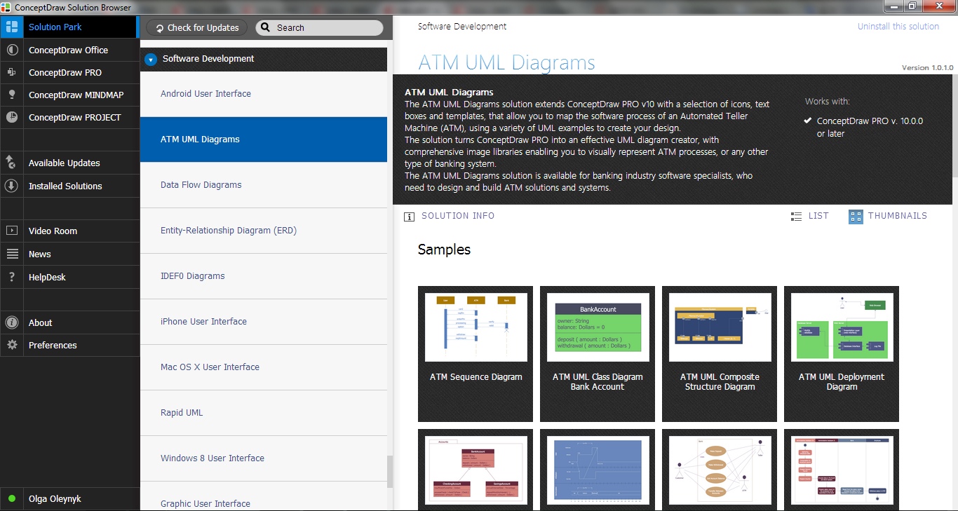
Diagramming Software for Design UML Package Diagrams


Swim Lane Flowchart Symbols

 Cross-Functional Flowcharts
Cross-functional flowcharts are powerful and useful tool for visualizing and analyzing complex business processes which requires involvement of multiple people, teams or even departments. They let clearly represent a sequence of the process steps, the order of operations, relationships between processes and responsible functional units (such as departments or positions).
UML Flowchart Symbols

 ConceptDraw Solution Park
ConceptDraw Solution Park collects graphic extensions, examples and learning materials
Introductory Guide to Rapid UML Solution

IDEF0 Flowchart Symbols

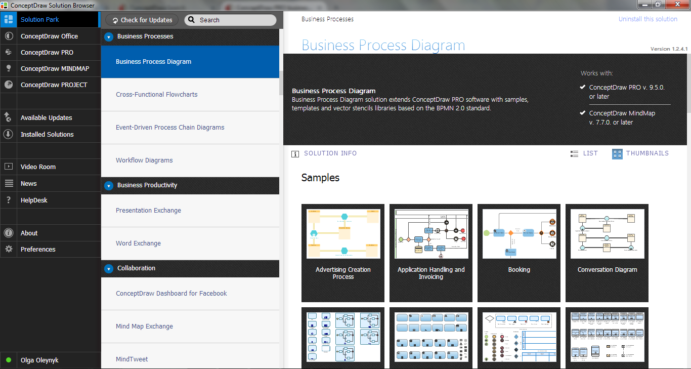
 Business Process Mapping
The Business Process Mapping solution for ConceptDraw DIAGRAM is for users involved in process mapping and creating SIPOC diagrams.
Entity-Relationship Diagram (ERD) with ConceptDraw DIAGRAM


ConceptDraw DIAGRAM
UML Use Case Diagram Example. Social Networking Sites Project

IDEF0 Visio

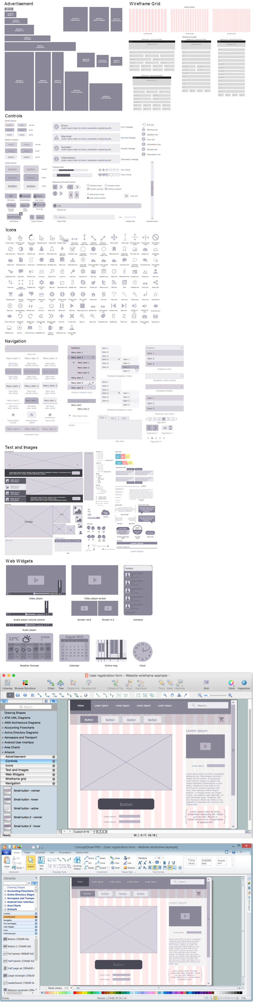
Wireframing
- Swim Lane Ppt
- Swim Lane Flowchart Symbols | ATM Solutions | ConceptDraw PRO ...
- ATM Solutions | Create PowerPoint Presentation from a Wireless ...
- UML Use Case Diagram Example. Social Networking Sites Project ...
- Swimlanes Ppt
- Interaction Overview Diagram | UML Collaboration Diagram ...
- Flow Chart Of An Atm Machine Process
- Bank Management System With Uml Diagrams Ppt
- Diagram Deployment Ppt
- Graphical Symbols to use in EPC diagrams | EPC | EPC IT Solutions ...
- Flowchart Showing Functioning Of Atm
- Uml Ppt Documents For Pdf
- UML Flowchart Symbols | Swim Lane Flowchart Symbols | Business ...
- Draw The Processing Logic For An Atm Machine
- Cross-Functional Flowcharts | Swim Lane Flowchart Symbols | ATM ...
- Swimlane Activity Diagram For Registration
- Bank System | Bank UML Diagram | Bank Sequence Diagram | Bank ...
- UML activity diagram - Cash withdrawal from ATM | UML Activity ...
- Process Flowchart | Flowcharts | UML Deployment Diagram ...