Swim Lane Flowchart Symbols

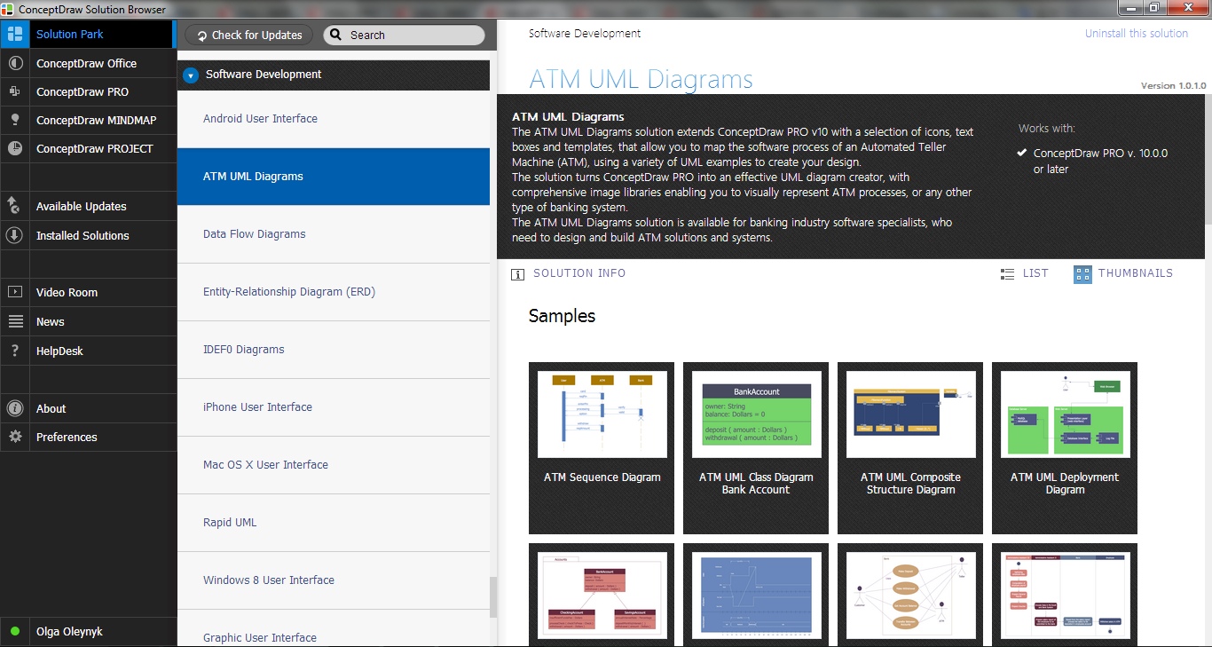
ATM Solutions
ConceptDraw DIAGRAM
UML Flowchart Symbols

Use Case Diagrams technology with ConceptDraw DIAGRAM

 ConceptDraw Solution Park
ConceptDraw Solution Park collects graphic extensions, examples and learning materials
UML Use Case Diagram Example - Estate Agency

Entity-Relationship Diagram (ERD) with ConceptDraw DIAGRAM


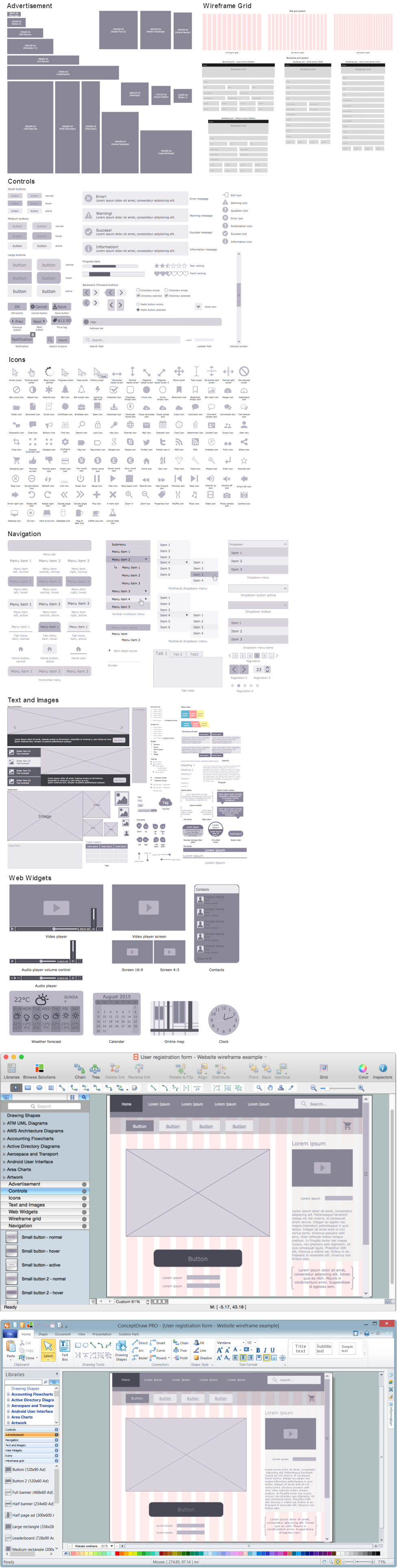
Wireframing
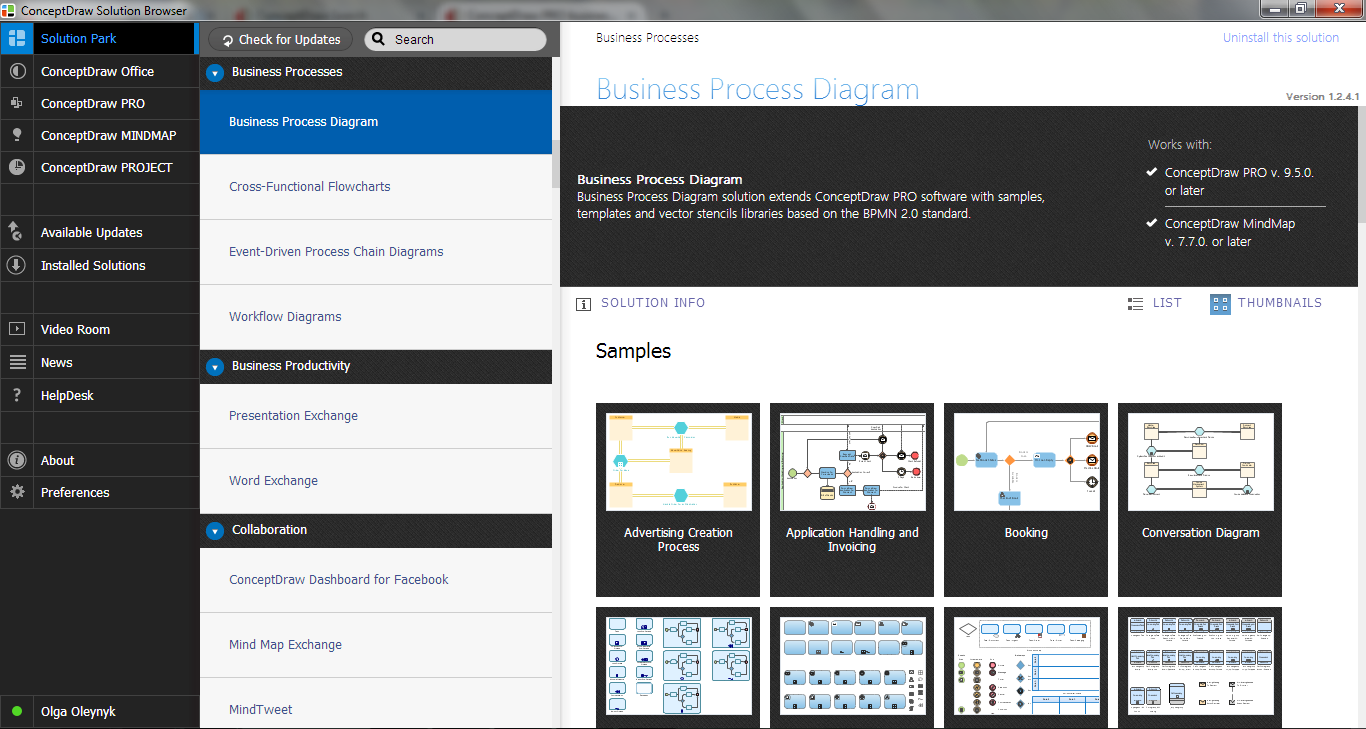
 Business Process Model and Notation
Business Process Model and Notation Solution for ConceptDraw DIAGRAM is helpful for modeling the business processes of any degree of complexity, documenting them and effective creating diagrams using the BPMN 2.0 standard.
Diagramming Software for Design UML Timing Diagrams


IDEF0 Visio

- Swim Lane Diagrams | ATM Solutions | UML activity diagram ...
- Cross-Functional Flowchart ( Swim Lanes ) | Swim Lane Flowchart ...
- Cross-Functional Flowchart ( Swim Lanes ) | Swim Lanes Flowchart ...
- Cross-Functional Flowcharts | Swim Lane Diagrams | Swim Lane ...
- Cross-Functional Flowcharts | Swim Lane Flowchart Symbols | ATM ...
- Automated payroll management system UML activity diagram | UML ...
- Swim Lane Flowchart Symbols | ATM Solutions | Design elements ...
- Swim Lane Diagrams | Swim Lanes Flowchart. Flowchart Examples ...
- Ppt On Atm Machine With Swimlane Diagram
- Automated payroll management system UML activity diagram | Swim ...
- Swim Lane Diagrams | Business Process Elements: Swimlanes ...
- Online Swim Lanes
- Multiple Use Case Diagram For The Atm Machine In Visual Modeling
- ATM Solutions | UML Activity Diagram | Swim Lane Flowchart ...
- Business Process Elements: Swimlanes | Business Process ...
- Swim Lanes Flowchart. Flowchart Examples | Swim Lane Diagrams ...
- Cross-Functional Flowcharts | Swim Lane Diagrams | Accounting ...
- UML activity diagram ( swimlanes ) - Template | Swim Lane Flowchart ...
- Cross-Functional Flowchart ( Swim Lanes ) | Swim Lane Flowchart ...
- Swim Lane Diagrams | Swim Lane Flowchart Symbols ...