Local area network (LAN). Computer and Network Examples
 diagram")

Metropolitan area networks (MAN). Computer and Network Examples
. Computer and Network Examples")
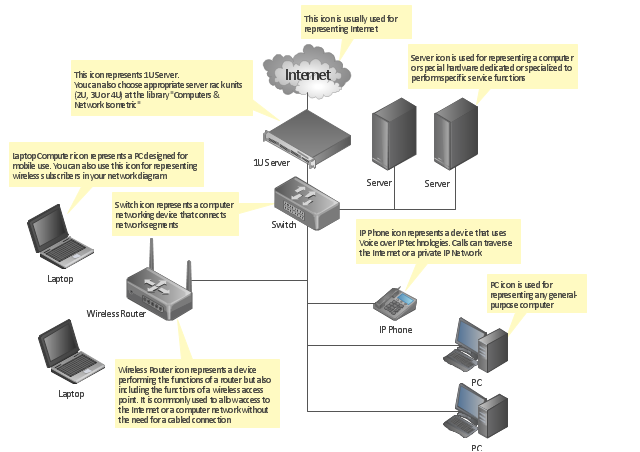
"A computer network diagram is a schematic depicting the nodes and connections amongst nodes in a computer network or, more generally, any telecommunications network. ...
Readily identifiable icons are used to depict common network appliances e.g. Router, and the style of lines between them indicate the type of connection. Clouds are used to represent networks external to the one pictured for the purposes of depicting connections between internal and external devices, without indicating the specifics of the outside network. ...
At different scales diagrams may represent various levels of network granularity. At the LAN level, individual nodes may represent individual physical devices, such as hubs or file servers, while at the WAN level, individual nodes may represent entire cities. In addition, when the scope of a diagram crosses the common LAN/ MAN/ WAN boundaries, representative hypothetical devices may be depicted instead of showing all actually existing nodes." [Computer network diagram. Wikipedia]
The computer network diagram template for the ConceptDraw PRO diagramming and vector drawing software is included in the Computer and Networks solution from the Computer and Networks area of ConceptDraw Solution Park.
Computer network diagram template
How to Draw a Computer Network Diagrams

Campus Area Networks (CAN). Computer and Network Examples
. <br>Computer and Network Examples *")
Wide area network (WAN) topology. Computer and Network Examples
 topology. <br>Computer and Network Examples *")
Personal area (PAN) networks. Computer and Network Examples
 networks")
Hybrid Network Topology

Geo Map - Africa - Chad

Cisco Media. Cisco icons, shapes, stencils and symbols

Cloud Computing Architecture Diagrams

Cisco Routers. Cisco icons, shapes, stencils and symbols

Network Topologies


Electrical Symbols, Electrical Diagram Symbols

Entity Relationship Diagram Symbols

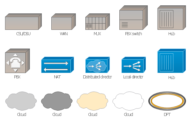
The vector stencils library "Cisco WAN" contains 15 symbols of wide area network (WAN) devices and equipment: CSU/ DSU (Channel Service Unit/ Data Service Unit), WAN, MUX (multiplexer), PBX switch, Hub, NAT (network address translation), distributed and local directors, PBX (private branch exchange), Network clouds, DPT (dynamic packet transport).
Create the computer network topology diagrams using the ConceptDraw PRO diagramming and vector drawing software with the design elements library "Cisco WAN".
"A wide area network (WAN) is a network that covers a broad area (i.e., any telecommunications network that links across metropolitan, regional, or national boundaries) using private or public network transports. Business and government entities utilize WANs to relay data among employees, clients, buyers, and suppliers from various geographical locations. In essence, this mode of telecommunication allows a business to effectively carry out its daily function regardless of location. The Internet can be considered a WAN as well, and is used by businesses, governments, organizations, and individuals for almost any purpose imaginable.
Related terms for other types of networks are personal area networks (PANs), local area networks (LANs), campus area networks (CANs), or metropolitan area networks (MANs) which are usually limited to a room, building, campus or specific metropolitan area (e.g., a city) respectively." [Wide area network. Wikipedia]
The example "Design elements - Cisco WAN" is included in the Cisco Network Diagrams solution from the Computer and Networks area of ConceptDraw Solution Park.
Cisco WAN symbols
Network Topology Illustration

Data Flow Diagrams

Network Diagram Software. LAN Network Diagrams. Physical Office Network Diagrams

Ring Network Topology

- Figure Of Lan Man Wan
- Draw A Figure Lan Man And Wan
- Local area network ( LAN ). Computer and Network Examples ...
- Fig Of Lan Man Wan Network
- Local area network ( LAN ). Computer and Network Examples ...
- Local area network ( LAN ). Computer and Network Examples ...
- Graphical Representation Of Lan Man Wan
- What Is The Use Of Lan And Wan And Figure
- Metropolitan area networks ( MAN ). Computer and Network Examples
- Local area network ( LAN ). Computer and Network Examples ...
- Figure Of Local Area Network
- Model Of Lan Man Wan
- Diagram Representation Of Lan Man Wan
- Explain Lan Man Wan With Diagrams
- Local area network ( LAN ). Computer and Network Examples ...
- Conbine Model On Networks Lan Man Wan
- Computer Network Diagrams | Expine Lan Man Wan
- Local area network ( LAN ). Computer and Network Examples | How ...
- Types Of Communication Channel Wan Lan Man
- Local area network ( LAN ). Computer and Network Examples ...