IDEF0 Visio

Network Diagram Software. LAN Network Diagrams. Physical Office Network Diagrams


Mechanical Drawing Software

Network Drawing Software

Network Diagram Software

Electrical Diagram Software


Electrical Drawing Software and Electrical Symbols

ConceptDraw Arrows10 Technology

Electrical Symbols — Integrated Circuit

Electrical Symbols, Electrical Diagram Symbols

Organic Chemistry Symbols

Electrical Symbols — Transmission Paths

Electrical Symbols — Switches and Relays

Electrical Symbols — Thermo

Electrical Symbols — Inductors

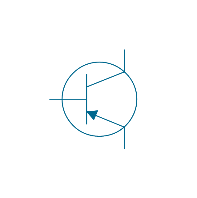
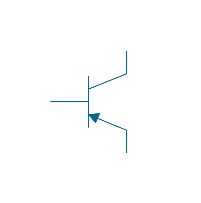
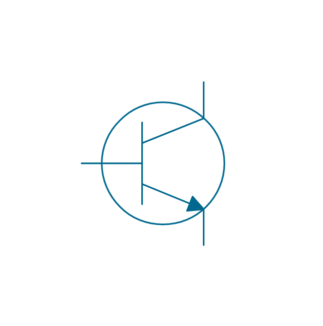
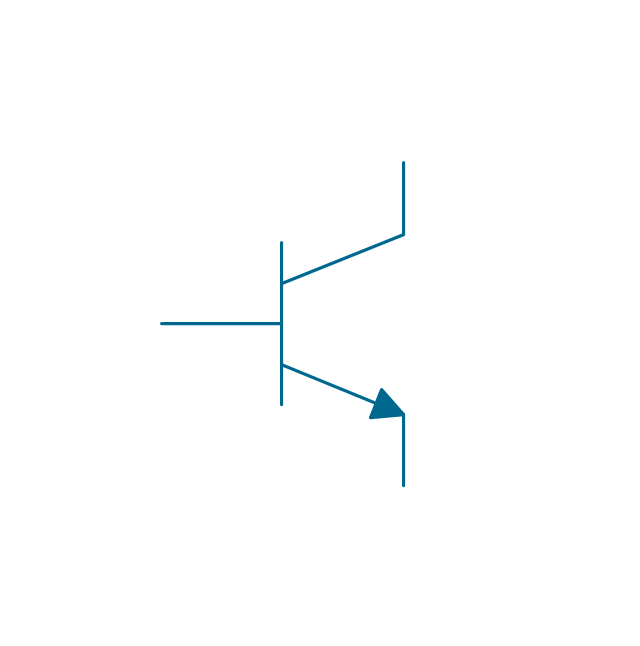
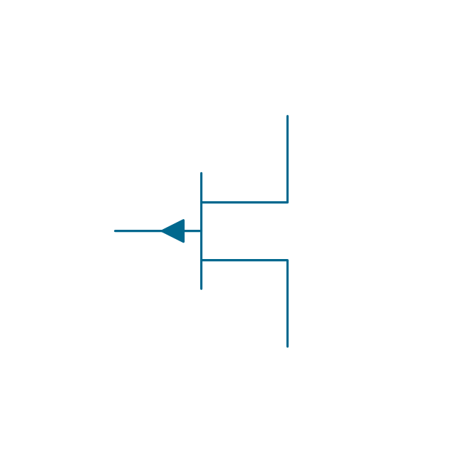
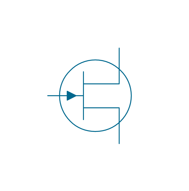
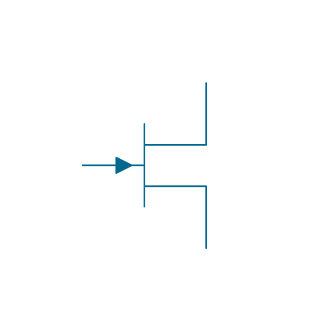
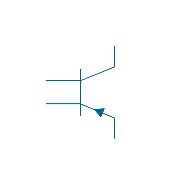
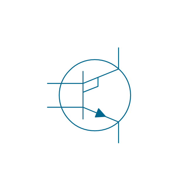
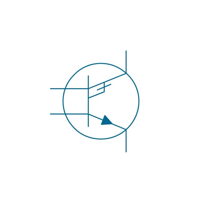
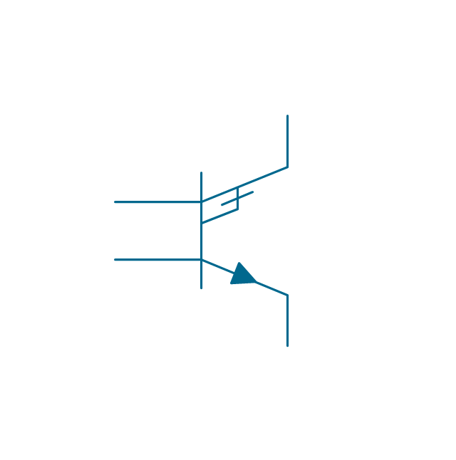
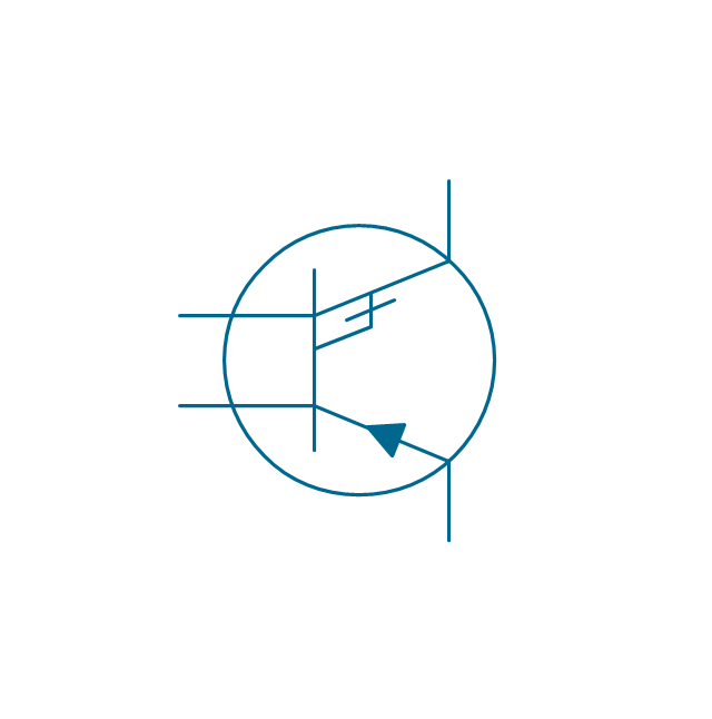
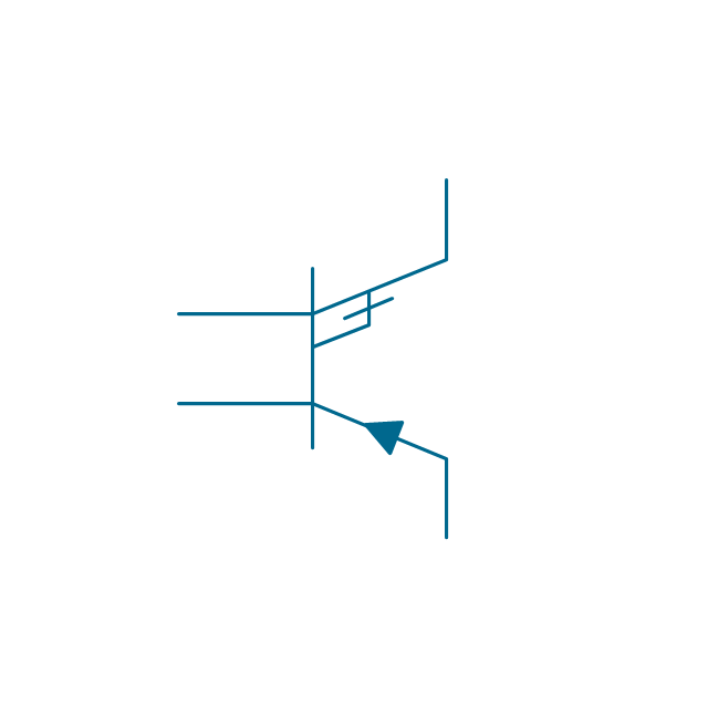
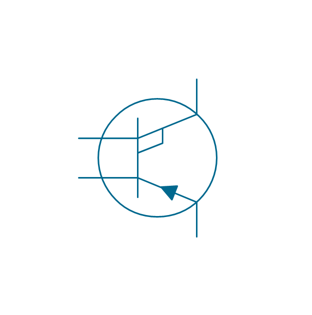
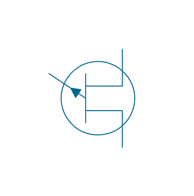
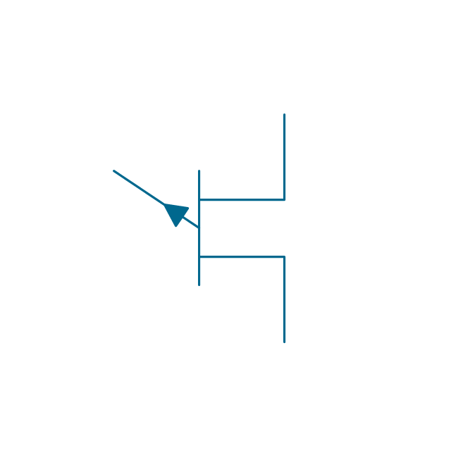
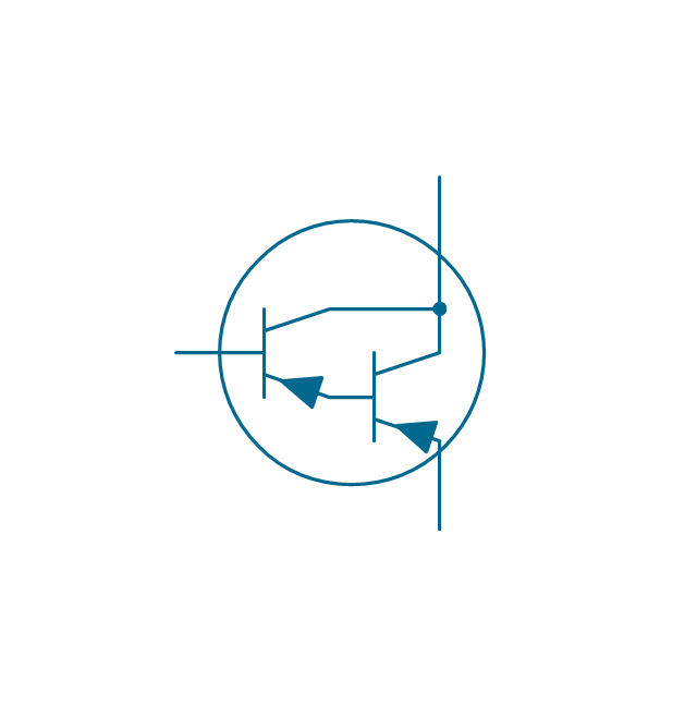
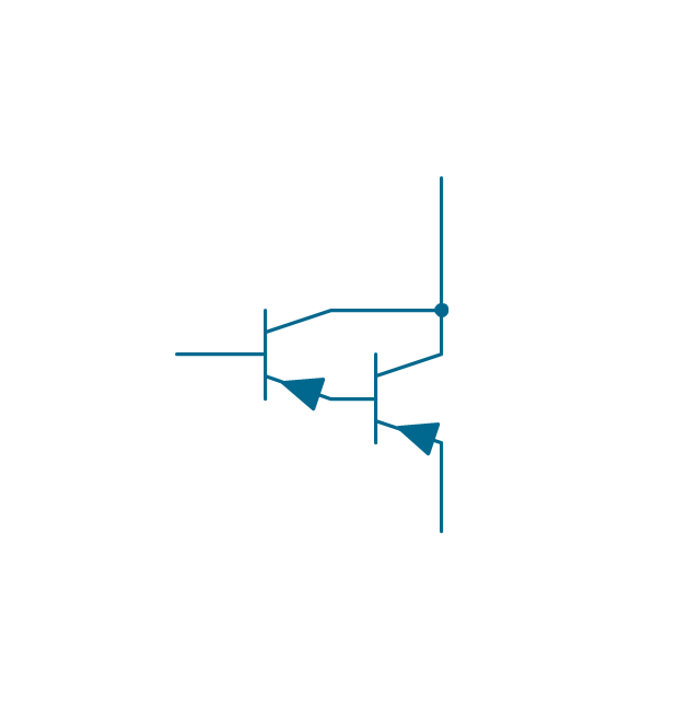
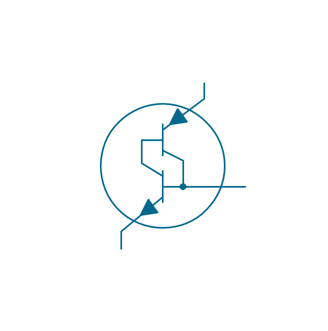
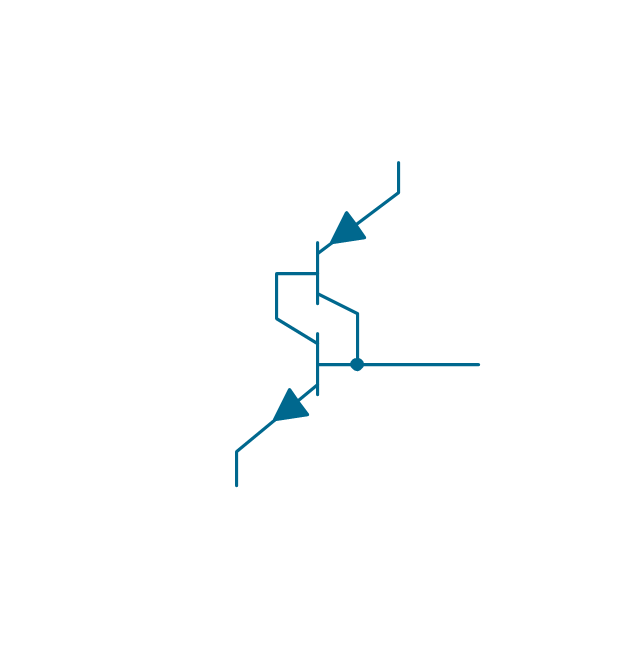
The vector stencils library "Transistors" contains 30 symbols of transistors.
Use these shapes for drawing electronic schematics and circuit diagrams in the ConceptDraw PRO diagramming and vector drawing software extended with the Electrical Engineering solution from the Engineering area of ConceptDraw Solution Park.
www.conceptdraw.com/ solution-park/ engineering-electrical
Use these shapes for drawing electronic schematics and circuit diagrams in the ConceptDraw PRO diagramming and vector drawing software extended with the Electrical Engineering solution from the Engineering area of ConceptDraw Solution Park.
www.conceptdraw.com/ solution-park/ engineering-electrical
BJT, PNP, env
BJT, PNP
BJT, NPN, env
BJT, NPN
JFET, P, env

JFET, P
JFET, N, env
JFET, N
Transverse biased base, PNP, env

Transverse biased base, PNP
Transverse biased base, NPN, env

Transverse biased base, NPN

Ohmic, NPIN, env
Ohmic, NPIN

Ohmic, NPIP, env
Ohmic, NPIP
Ohmic, PNIN, env
Ohmic, PNIN
Ohmic, PNIP, env
Ohmic, PNIP

Unijunction FET, P, env
Unijunction FET, P
Unijunction FET, N, env

Unijunction FET, N

Darlington transistor, PNP, env
Darlington transistor, PNP
Darlington transistor, NPN, env
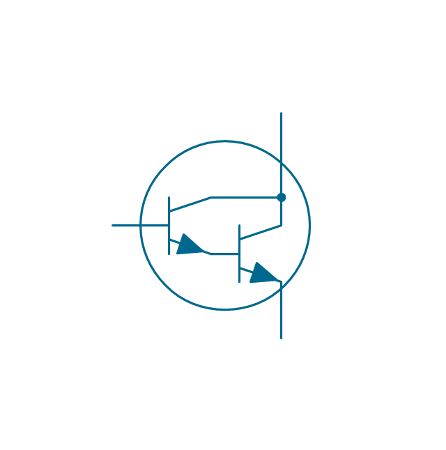
Darlington transistor, NPN

Transistor latch, env
Transistor latch
Electrical Symbols — Composite Assemblies

Electrical Symbols — Resistors

Electrical Symbols — Delay Elements

Electrical Symbols — Logic Gate Diagram

- Electrical Symbols — MOSFET | Electrical Symbols — IGFET ...
- Electrical Symbols — Transistors | Design elements - Transistors ...
- Electrical Diagram | Residential Electric Plan | Electric Visual | Ppt ...
- Design elements - Transistors | Design elements - Semiconductor ...
- Mechanical Fabrication Drawing Symbols
- Process Flowchart | Technical drawing - Machine parts assembling ...
- Electrical Symbols — Transistors | Electrical Symbols — MOSFET ...
- Electrical Symbols — Semiconductor | In searching of alternative to ...
- Visio Cylinder Shape
- How To Draw Electrical Block Diagram Of Electrical Circuit In Visio
- Subway Train Map | Metro Train Map | Rail transport - Design ...
- Mechanical Drawing Symbols | Electrical Symbols, Electrical ...
- MOSFET
- Visio Mosfet Symbol
- Electrical Symbols, Electrical Diagram Symbols | How To use House ...
- Process Flow Diagram Symbols | Process Flowchart | Technical ...
- Microsoft Visio Electrical Symbols Free Download
- Visio Electrical Symbols
- Electrical Symbols, Electrical Diagram Symbols | Process Flow ...