Electrical Symbols — MOSFET

Electrical Symbols — IGFET

Electrical Symbols, Electrical Diagram Symbols

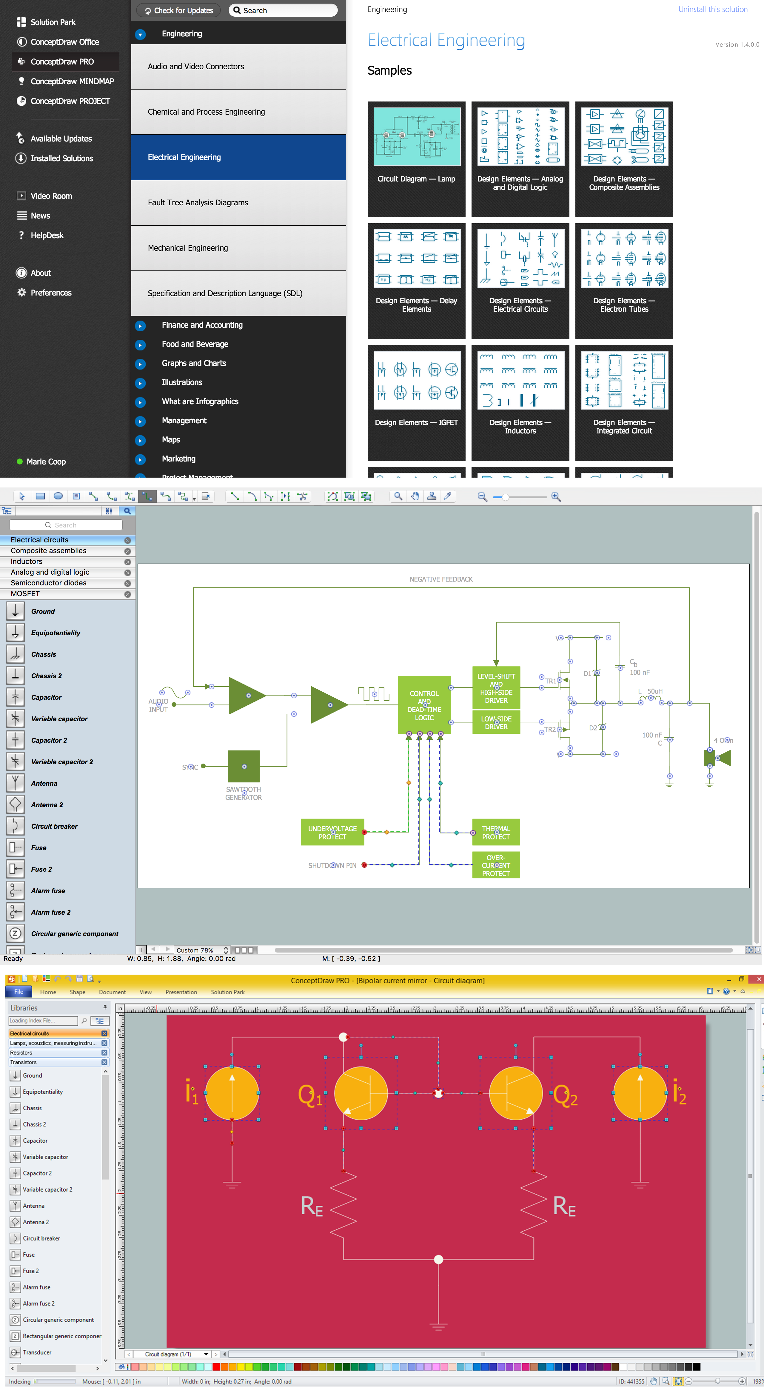
 Electrical Engineering
This solution extends ConceptDraw DIAGRAM.9.5 (or later) with electrical engineering samples, electrical schematic symbols, electrical diagram symbols, templates and libraries of design elements, to help you design electrical schematics, digital and analog
Electrical Symbols — Logic Gate Diagram

Electrical Symbols — Transmission Paths
Electrical Symbols — Resistors

Wiring Diagrams with ConceptDraw DIAGRAM
Electrical Diagram

Electrical Symbols — Transistors
- Visio Mosfet Symbol
- Electrical Engineering | Mosfet Visio
- Electrical Engineering | Electronic Visio Mosfet
- Visio Transistor
- Drawing Transistors With Visio
- Visio Integrated Circuit
- Voltage Controlled Current Source Visio
- Payment Terminal Visio Stencil
- Design elements - Transistors | Design elements - Semiconductor ...