
Example 1. Electrical Diagram - Simple Switched Supply
Electrical Symbols
First of all, the Electrical Engineering Solution provides a huge collection of ready-to-use predesigned elements. These are 926 electrical symbols grouped in 26 libraries:
- Analog and Digital Logic
- Composite Assemblies
- Delay Elements
- Electrical Circuits
- Electron Tubes
- IGFET
- Inductors
- Integrated Circuit
- Lamps, Acoustics, Readouts
- Logic Gate Diagram
- MOSFET
- Maintenance
- Power Sources
- Qualifying
- Resistors
- Rotating Equipment
- Semiconductor Diodes
- Semiconductors
- Stations
- Switches and Relays
- Terminals and Connectors
- Thermo
- Transformers and Windings
- Transistors
- Transmission Paths
- VHF UHF SHF
All these libraries and their samples are available from Electrical Engineering Solution section in ConceptDraw STORE.

Example 2. Electrical Symbols in ConceptDraw STORE
To design Electrical Diagram: create new ConceptDraw document, simply drag appropriate elements from the libraries to this document and arrange them in a desirable way.

Example 3. Electrical Diagram - Bipolar Current Mirror
The set of electrical diagram samples you see on this page was created in ConceptDraw DIAGRAM software using the tools of Electrical Engineering Solution. An experienced user spent 10-15 minutes creating each of these samples.
Use the Electrical Engineering Solution for ConceptDraw DIAGRAM software to create your own professional looking electrical diagram fast, easy and effective.
All source documents are vector graphic documents. They are available for reviewing, modifying, or converting to a variety of formats (PDF file, MS PowerPoint, MS Visio, and many other graphic formats) from the ConceptDraw STORE. The Electrical Engineering Solution is available for all ConceptDraw DIAGRAM or later users.
NINE RELATED HOW TO's:
A Telecommunications network is a network of nodes, links, trunks and telephone switches that are connected, operated by telephone companies and realize telephone, audio, visual and data communications among the users. The telecommunications network can also include Internet, microwave, wireless equipment.
This example was created in ConceptDraw DIAGRAM using the Computer and Networks Area of ConceptDraw Solution Park and shows the Telecommunications network.
Picture: Telecommunication networks. Computer and Network Examples
Related Solution:
The Building Plans are very useful and even necessary for architects, builders, designers and simple for those who want to build the home, office, flat or anyone other building. They are also convenient for those who want to design or redesign the home, flat, room, etc.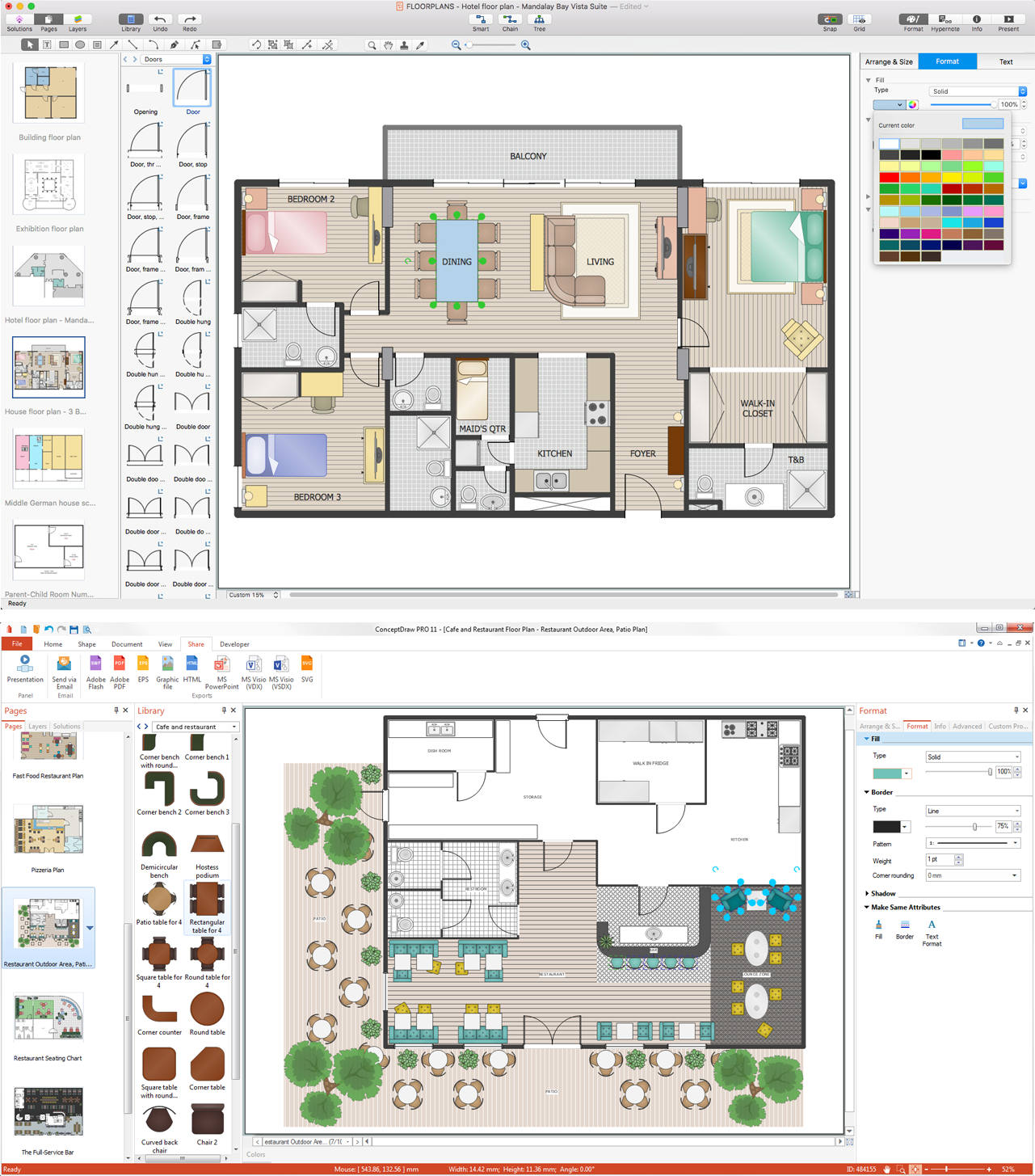
Picture: Building Plan Software. Building Plan Examples
Related Solution:
Chemistry solution offers 6 libraries with large collection of vector chemistry symbols and meanings, chemistry equation symbols, organic chemistry symbols, and chemical clipart.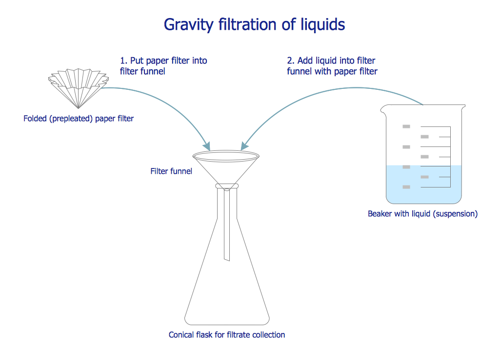
Picture: Chemistry Symbols and Meanings
Related Solution:
Special libraries of highly detailed, accurate shapes and computer graphics, servers, hubs, switches, printers, mainframes, face plates, routers etc.
Picture: Network Printer
ConceptDraw DIAGRAM extended with Pictorial Infographics Solution from the “Infographics” Area is a powerful Infographic Software. Make sure in it right now!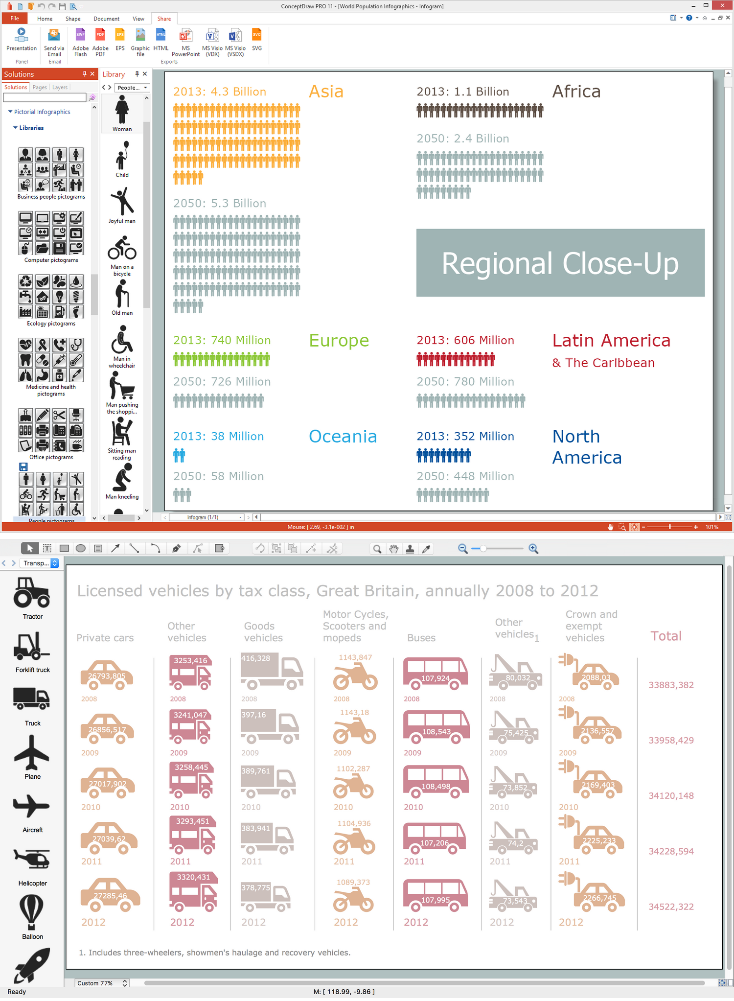
Picture: Infographic Software
Related Solution:
Infographic Design Elements for visually present various geographically distributed information.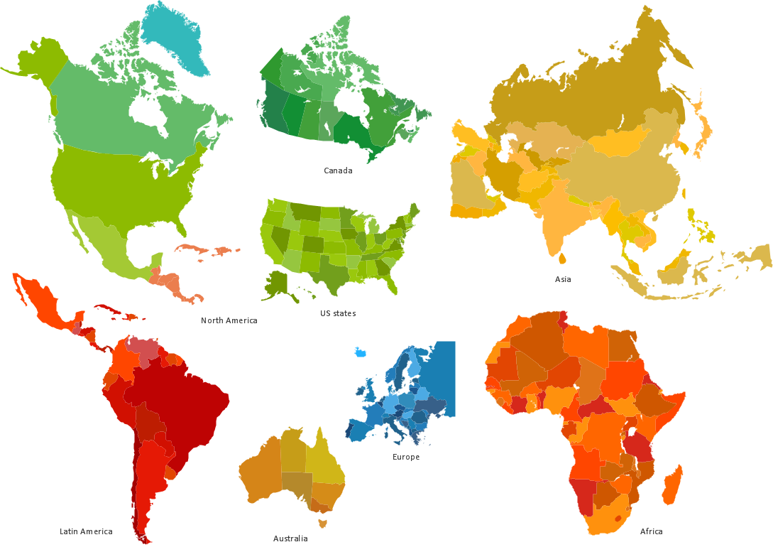
Picture: Spatial infographics Design Elements: Location Map
ConceptDraw DIAGRAM is a powerful diagramming and vector drawing software. Extended with Chemical and Process Engineering Solution from the Industrial Engineering Area of ConceptDraw Solution Park, it became the best Chemical Engineering software.
Picture: Chemical Engineering
Related Solution:
Infrastructure is very important part of any district, and educational buildings presence is one of the factors. Another not less important thing is the school design, because it influences the children's’ sense of aesthetics. To develop a harmonic school layout, use a proper software.
This image represents the School layout library that is supplied with ConceptDraw School and Training Plans solution. The library contains a set of vector graphic objects that will be in help while drawing a layout of classroom. Any lecturer desires to organize the layout of the classroom for the best student advantage. Students must be focused and be engaged in the learning process. The classroom places organization is an important element of a students learning. It is significant for a lecturer to set up a classroom layout and change it time to time to support lectures, to invoke disputes or solve any organizational issues. By using ConceptDraw DIAGRAM you can easily plan how to re-arrange the desks in the class room to maintain visual control of your class and build a friendly environment in the classroom.
Picture: Building Drawing Software for Design School Layout
Related Solution:
Rhineland-Palatinate is a southwest German state bordered by France, Belgium and Luxembourg. The capital city is Mainz.
Despite the fact that the maps surround us everywhere in our life, usually the process of their drawing is sufficienly complex and labor-intensive. But now, thanks to the ConceptDraw DIAGRAM diagramming and vector drawing software extended with Germany Map Solution from the Maps Area of ConceptDraw Solution Park, we have the possibility to make easier this process. Design fast and easy your own pictorial maps of Germany, map of Germany with cities, and thematic Germany maps in ConceptDraw DIAGRAM!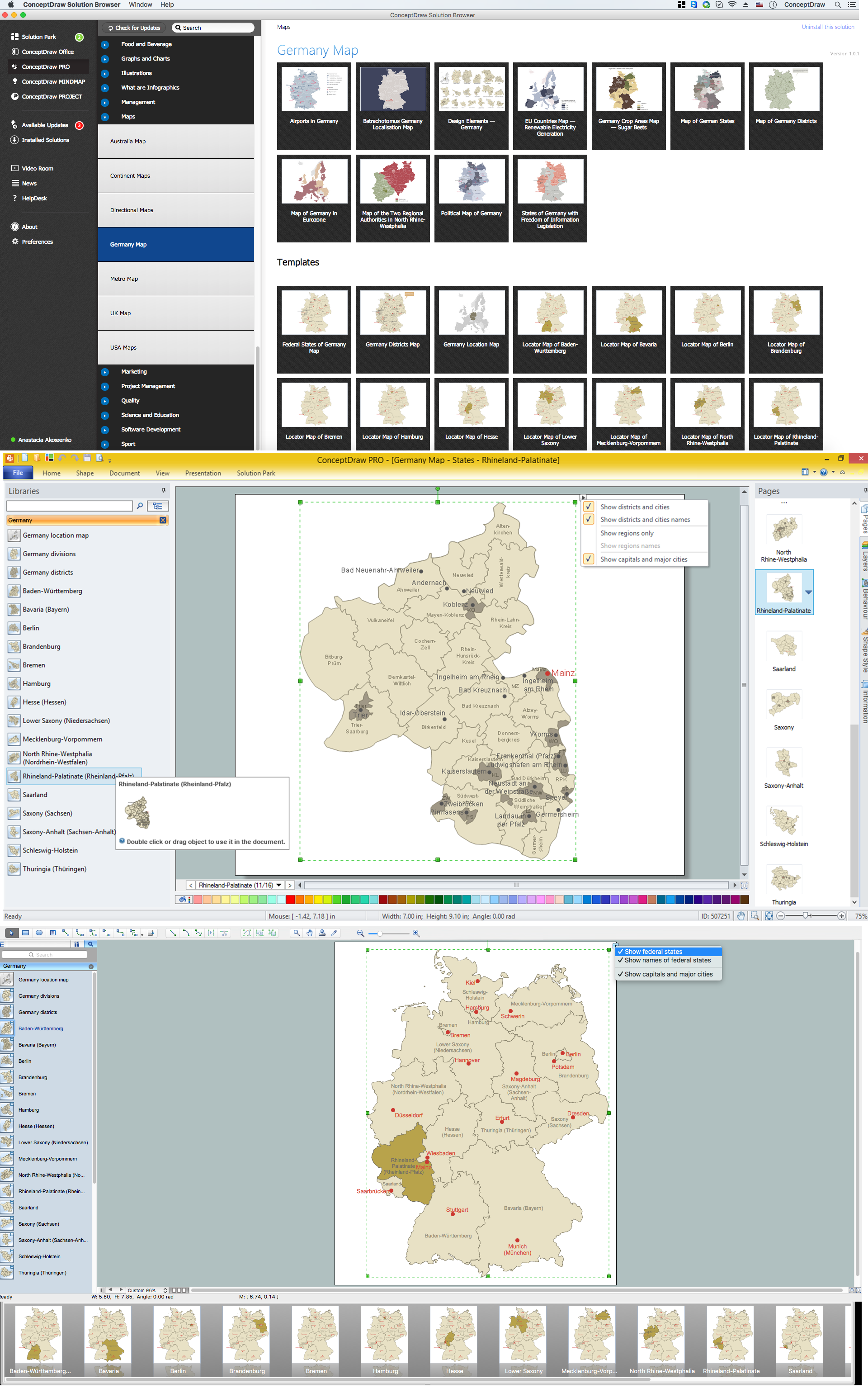
Picture: Map of Germany — Rhineland-Palatinate State
Related Solution:

