Electrical Symbols — Thermo

Process Flow Diagram Symbols

Electrical Symbols — Inductors

Local area network (LAN). Computer and Network Examples
 diagram")

Technical Drawing Software

Mechanical Drawing Software

Wiring Diagrams with ConceptDraw DIAGRAM

Flowchart Components

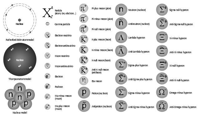
The vector shapes library "Nuclear physics" contains 39 symbol icons of elementary particles.
Use these shapes for drawing nuclear physics diagrams of nuclear reactions and experiments in the ConceptDraw PRO diagramming and vector drawing software extended with the Physics solution from the Science and Education area of ConceptDraw Solution Park.
www.conceptdraw.com/ solution-park/ science-education-physics
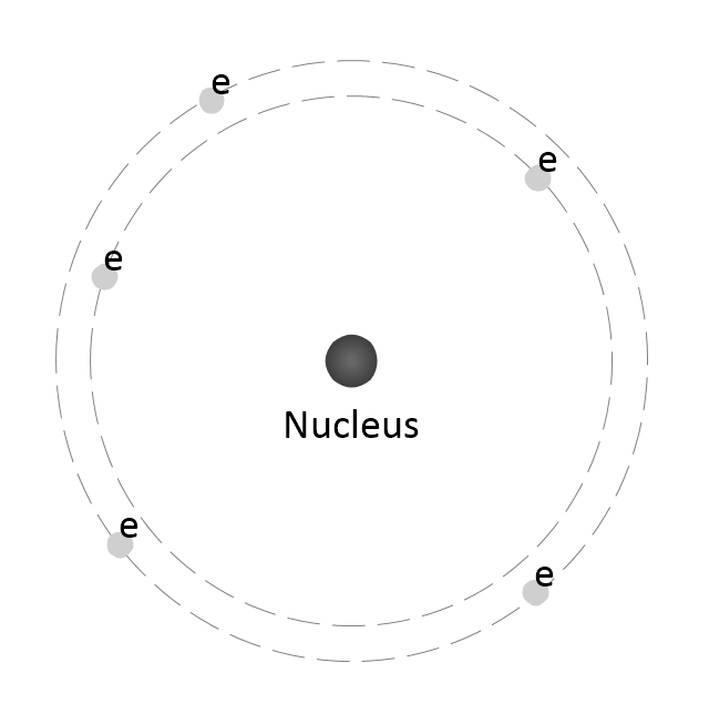
Rutherford Atom Model
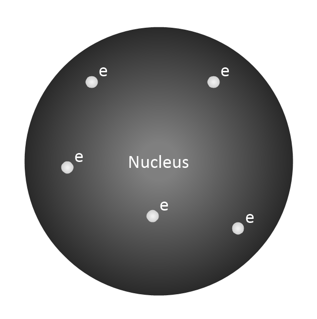
Thompson Atom Model
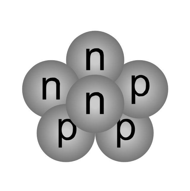
Nucleus model
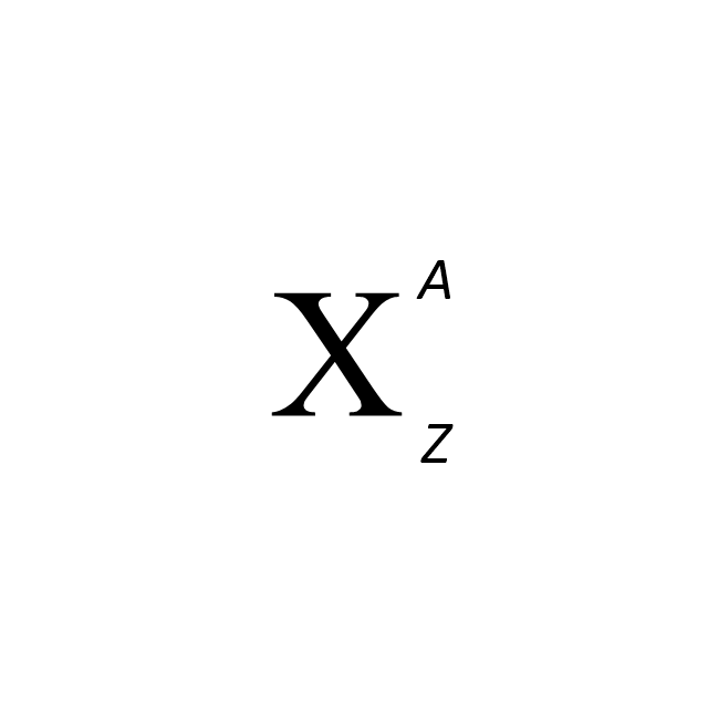
Particle
Gamma particle

Electron neutrino
Electron antineutrino

Muon neutrino

Muon antineutrino

Electron

Positron

Mu-minus meson (muon)
-nuclear-physics---vector-shapes-library.png--diagram-flowchart-example.png)
Mu-plus meson (muon)
-nuclear-physics---vector-shapes-library.png--diagram-flowchart-example.png)
Pi-plus meson (pion)
-nuclear-physics---vector-shapes-library.png--diagram-flowchart-example.png)
Pi-minus meson (pion)
-nuclear-physics---vector-shapes-library.png--diagram-flowchart-example.png)
K-plus meson (kaon)
-nuclear-physics---vector-shapes-library.png--diagram-flowchart-example.png)
Pi-null meson (pion)
-nuclear-physics---vector-shapes-library.png--diagram-flowchart-example.png)
K-minus meson (kaon)
-nuclear-physics---vector-shapes-library.png--diagram-flowchart-example.png)
K-null meson (kaon)
-nuclear-physics---vector-shapes-library.png--diagram-flowchart-example.png)
Anti-K-null meson (antikaon)
-nuclear-physics---vector-shapes-library.png--diagram-flowchart-example.png)
Eta-meson
Proton (nucleon)
-nuclear-physics---vector-shapes-library.png--diagram-flowchart-example.png)
Antiproton (nucleon)
-nuclear-physics---vector-shapes-library.png--diagram-flowchart-example.png)
Neutron (nucleon)
-nuclear-physics---vector-shapes-library.png--diagram-flowchart-example.png)
Antineutron (nucleon)
-nuclear-physics---vector-shapes-library.png--diagram-flowchart-example.png)
Lambda-hyperon

Anti-Lambda hyperon
Sigma-plus-hyperon

Anti-Sigma-minus-hyperon
Anti-Sigma-plus-hyperon

Sigma-minus-hyperon

Sigma-null-hyperon
Anti-Sigma-null hyperon
Xi-minus-hyperon

Anti-Xi-minus hyperon

Xi-null-hyperon

Anti-Xi-null-hyperon
Omega-minus-hyperon
Anti-Omega-minus-hyperon
Electrical Symbols — Analog and Digital Logic

Entity Relationship Diagram Examples


Physics Symbols

Cisco Network Topology. Cisco icons, shapes, stencils and symbols

Network Diagram Software. LAN Network Diagrams. Physical Office Network Diagrams

The vector stencils library "Fault tree analysis diagrams" contains 12 symbols for drawing FTA diagrams in the ConceptDraw PRO diagramming and vector drawing software extended with the Fault Tree Analysis Diagrams solution from the Engineering area of ConceptDraw Solution Park.
www.conceptdraw.com/ solution-park/ engineering-fault-tree-analysis-diagrams
www.conceptdraw.com/ solution-park/ engineering-fault-tree-analysis-diagrams
AND gate

Priority AND gate

OR gate

Inhibit gate

XOR gate

Event

Basic event

Undeveloped event

House event

Conditional event

Transfer symbol

Voting gate

Chemical Engineering

Fault Tree Analysis Software

The vector shapes library "Nuclear physics" contains 39 symbol icons of elementary particles for drawing diagrams of nuclear reactions and experiments in nuclear physics.
"Nuclear physics is the field of physics that studies the constituents and interactions of atomic nuclei. The most commonly known applications of nuclear physics are nuclear power generation and nuclear weapons technology, but the research has provided application in many fields, including those in nuclear medicine and magnetic resonance imaging, ion implantation in materials engineering, and radiocarbon dating in geology and archaeology.
The field of particle physics evolved out of nuclear physics and is typically taught in close association with nuclear physics." [Nuclear physics. Wikipedia]
The example "Design elements - Nuclear physics" was created using the ConceptDraw PRO diagramming and vector drawing software extended with the Physics solution from the Science and Education area of ConceptDraw Solution Park.
Elementary particles
How to Build a Flowchart

 SYSML
SYSML
The SysML solution helps to present diagrams using Systems Modeling Language; a perfect tool for system engineering.
- Lighting Drawing Symbol
- Symbol Of Transmitter
- Mechanical Drawing Symbols | Process Flow Diagram Symbols ...
- Ceiling Spot Light Symbol
- Electrical Symbols, Electrical Diagram Symbols | Tubelight Symbol
- Lighting Symbol For For Drawing
- Symbol Rotary Pump
- Electrical Symbols — Logic Gate Diagram | How to Create a Fault ...
- Mechanical Engineering Project Drawings Of Power Plant
- Chemical elements - Vector stencils library | Design elements ...
- Nuclear physics - Vector shapes library | Design elements - Nuclear ...
- Pendant Light Symbol
- Electrical Symbols — Resistors | Electrical Symbols — Analog and ...
- Mechanical Operations And Symbol In Pdf
- Physics | How to Draw Physics Diagrams in ConceptDraw PRO ...
- Symbol Of Atwin Fluorescent Lamp
- Gd And T Symbol
- How To Draw Plumbing Plans
- Chemistry Symbols and Meanings | Organic Chemistry Symbols ...
- Symbol Of Ramp