Bus Network Topology

Hybrid Network Topology

Network Configuration


"A bus network is a network topology in which nodes are connected in a daisy chain by a linear sequence of buses. ...
The bus is the data link in a bus network. The bus can only transmit data in one direction, and if any network segment is severed, all network transmission ceases.
A host on a bus network is called a station or workstation. In a bus network, every station receives all network traffic, and the traffic generated by each station has equal transmission priority. Each network segment is, therefore, a collision domain. In order for nodes to transmit on the same cable simultaneously, they use a media access control technology such as carrier sense multiple access (CSMA) or a bus master." [Bus network. Wikipedia]
The bus network topology diagram example was created using the ConceptDraw PRO diagramming and vector drawing software extended with the Computer and Networks solution from the Computer and Networks area of ConceptDraw Solution Park.
Bus topology

Wide area network (WAN) topology. Computer and Network Examples
 topology. <br>Computer and Network Examples *")
Star Network Topology


Cisco Network Topology. Cisco icons, shapes, stencils and symbols

Physical network. Computer and Network Examples

Complete Network Topology

"Logical topology, or signal topology, is the arrangement of devices on a computer network and how they communicate with one another. How devices are connected to the network through the actual cables that transmit data, or the physical structure of the network, is called the physical topology. Physical topology defines how the systems are physically connected. It represents the physical layout of the devices on the network. The logical topology defines how the systems communicate across the physical topologies.
Logical topologies are bound to network protocols and describe how data is moved across the network. ...
EXAMPLE : twisted pair Ethernet is a logical bus topology in a physical star topology layout. while IBM's token ring is a logical ring topology, it is physically set up in star topology." [Logical topology. Wikipedia]
This Cisco logical computer network diagram example was created using the ConceptDraw PRO diagramming and vector drawing software extended with the Cisco Network Diagrams solution from the Computer and Networks area of ConceptDraw Solution Park.
Logical network topology diagram

ATM Network. Computer and Network Examples

Phone networks. Computer and Network Examples

Network Topology

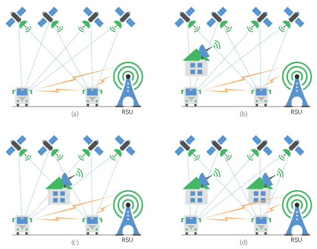
This diagram sample shows the different situations that cooperative positioning may be helpful for vehicular networks. It was designed on the base of Wikimedia Commons file: CPsituations.jpg.
[commons.wikimedia.org/ wiki/ File:CPsituations.jpg]
"Vehicular Ad Hoc Networks (VANETs) are created by applying the principles of mobile ad hoc networks (MANETs) - the spontaneous creation of a wireless network for data exchange - to the domain of vehicles. They are a key component of intelligent transportation systems (ITS).
While, in the early 2000s, VANETs were seen as a mere one-to-one application of MANET principles, they have since then developed into a field of research in their own right. By 2015, the term VANET became mostly synonymous with the more generic term inter-vehicle communication (IVC), although the focus remains on the aspect of spontaneous networking, much less on the use of infrastructure like Road Side Units (RSUs) or cellular networks." [Vehicular ad hoc network. Wikipedia]
The vehicular network diagram example "CP situations" was created using the ConceptDraw PRO diagramming and vector drawing software extended with the Computers and Communications solution from the Illustration area of ConceptDraw Solution Park.
Telecommunication diagram
Network Topologies

OSPF Network. Computer and Network Examples

Road Transport - Design Elements

Virtual private networks (VPN). Computer and Network Examples
. <br>Computer and Network Examples *")
The vector stencils library "Network layout floorplan" contain 34 symbol icons for drawing computer network floor plans, communication equipment layouts, and structured cabling diagrams.
"Structured cabling is building or campus telecommunications cabling infrastructure that consists of a number of standardized smaller elements (hence structured) called subsystems. ...
Structured cabling design and installation is governed by a set of standards that specify wiring data centers, offices, and apartment buildings for data or voice communications using various kinds of cable, most commonly category 5e (CAT-5e), category 6 (CAT-6), and fibre optic cabling and modular connectors. These standards define how to lay the cabling in various topologies in order to meet the needs of the customer, typically using a central patch panel (which is normally 19 inch rack-mounted), from where each modular connection can be used as needed. Each outlet is then patched into a network switch (normally also rack-mounted) for network use or into an IP or PBX (private branch exchange) telephone system patch panel." [Structured cabling. Wikipedia]
The design elements example "Network layout floorplan - Vector stencils library" was created using the ConceptDraw PRO diagramming and vector drawing software extended with the Network Layout Floor Plans solution from the Computer and Networks area of ConceptDraw Solution Park.
PC

Scanner

Switch

Router

Modem

Hub

Rack Mount

Printer

Floor Mounted Outlet

Single Outlet

Duplex Outlet

Direct bus cable

Tops or bottoms bus cable

Side to side bus cable

Multi-tree bus cable

Bottom to side bus cable

Sides bus cable

Door

Door, threshold

Door, stop

Door, stop, threshold

Door, frame

Door, frame, threshold

Door, frame, stop

Door, frame, stop, threshold

Window

Window, sill

Window, sash

Window, sash, sill

Window, frame

Window, frame, sill

Window, frame, sash

Window, frame, sash, sill

Tree Network Topology Diagram

- Bus network topology diagram | Network Diagram Examples | Basic ...
- Draw Bus Topology
- Network Diagram Examples | Basic Network Diagram | Bus network ...
- Network Diagram Examples | Bus network topology diagram ...
- Network Layout | Network Diagram Examples | Design Element ...
- Bus network topology diagram | Automatic vehicle location | Network ...
- Bus Network Topology | Hybrid Network Topology | Network ...
- Data Flow Diagram Level 0 1 2 Examples Online Bus Ticket
- Daily Life Examples Of Bus Topology
- Daily Life Examples Of Bus Topology
- Network Diagram Examples | Network Hubs | Logical symbols ...
- Network Diagram Examples | MS Visio Look a Like Diagrams | Bus ...
- Network Diagram Examples | Tree Network Topology Diagram ...
- Network Diagram Examples | Bus network topology diagram | Real ...
- Flow Chart Example Of Bus Company
- Network Diagram Examples | Draw Network Diagram based on ...
- Bus network topology diagram | Network Diagram Examples ...
- How To Draw Bus Topology
- Draw A Collaboration Diagram For Purchasing A Bus Ticket