Electrical Symbols — Transistors

Electrical Symbols — Thermo

Electrical Symbols — Semiconductor Diodes

Electrical Symbols — Semiconductor

Electrical Symbols — MOSFET

Electrical Diagram Software


Electrical Symbols — Stations

Electrical Symbols — VHF UHF SHF

Electrical Symbols — Electron Tubes

Electrical Diagram

Network Glossary Definition


Electrical Engineering

The vector stencils library "Design elements - Electron tubes" contains 36 element symbols of electron tubes.
Use it for drawing electrical schematics and electronic circuit diagrams.
"One classification of vacuum tubes is by the number of active electrodes, (neglecting the filament or heater). A device with two active elements is a diode, usually used for rectification. Devices with three elements are triodes used for amplification and switching. Additional electrodes create tetrodes, pentodes, and so forth, which have multiple additional functions made possible by the additional controllable electrodes.
Other classifications are:
(1) by frequency range (audio, radio, VHF, UHF, microwave),
(2) by power rating (small-signal, audio power, high-power radio transmitting),
(3) by design (e.g., sharp- versus remote-cutoff in some pentodes),
(4) by application (receiving tubes, transmitting tubes, amplifying or switching, rectification, mixing),
(5) special qualities (long life, very low microphonic and low noise audio amplification, and so on).
Multiple classifications may apply to a device; for example similar dual triodes can be used for audio preamplification and as flip-flops in computers, although linearity is important in the former case and long life in the latter.
Tubes have different functions, such as cathode ray tubes which create a beam of electrons for display purposes (such as the television picture tube) in addition to more specialized functions such as electron microscopy and electron beam lithography. X-ray tubes are also vacuum tubes. Phototubes and photomultipliers rely on electron flow through a vacuum, though in those cases electron emission from the cathode depends on energy from photons rather than thermionic emission." [Vacuum tube. Wikipedia]
The symbols example "Design elements - Electron tubes" was drawn using the ConceptDraw PRO diagramming and vector drawing software extended with the Electrical Engineering solution from the Engineering area of ConceptDraw Solution Park.
Vacuum tubes

Value Stream Diagram

Electrical Design Software

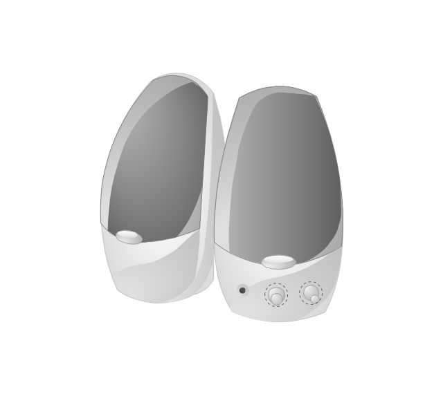
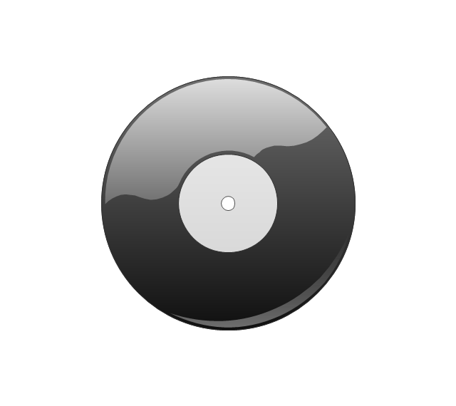
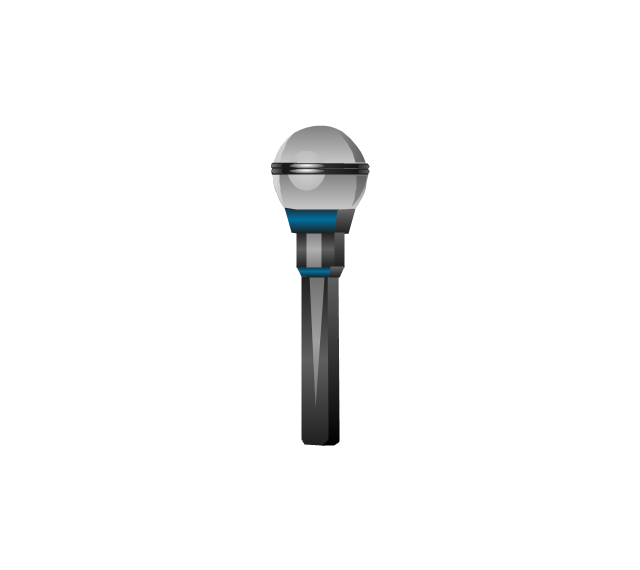
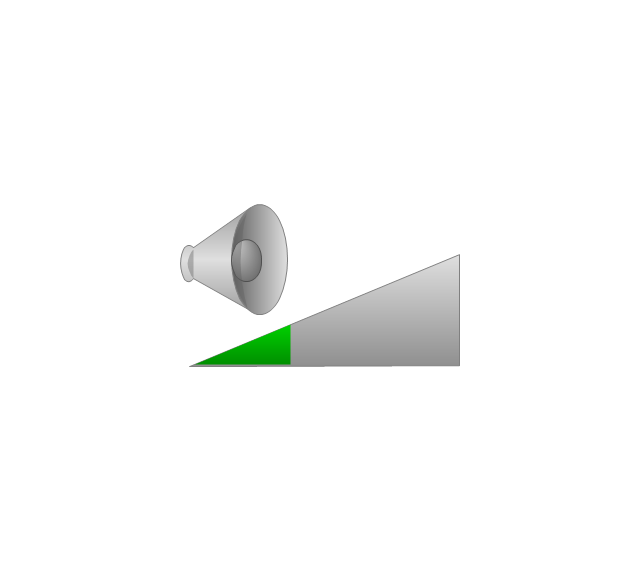
The vector stencils library "Music" contains 28 clipart images of musical devices, instruments and note signs for drawing illustrations.
"Music notation or musical notation is any system used to visually represent aurally perceived music through the use of written symbols, including ancient or modern musical symbols. Although many ancient cultures used symbols to represent melodies, none of them is nearly as comprehensive as written language, limiting the knowledge of ancient music to a few fragments. Comprehensive music notation began to be developed in Europe in the Middle Ages and has been adapted to many kinds of music worldwide." [Musical notation. Wikipedia]
The clip art example "Music - Vector stencils library" was created using the ConceptDraw PRO diagramming and vector drawing software extended with the Artwork solution from the Illustration area of ConceptDraw Solution Park.
www.conceptdraw.com/ solution-park/ illustrations-artwork
Speakers
Mute

Vinyl record
Compact Disk

Note

Two beamed notes

Eighth note

Headphones

Microphone
Loudness

Silent
Harp
Violin
Electric guitar
Acoustic Guitar

Drum

Piano
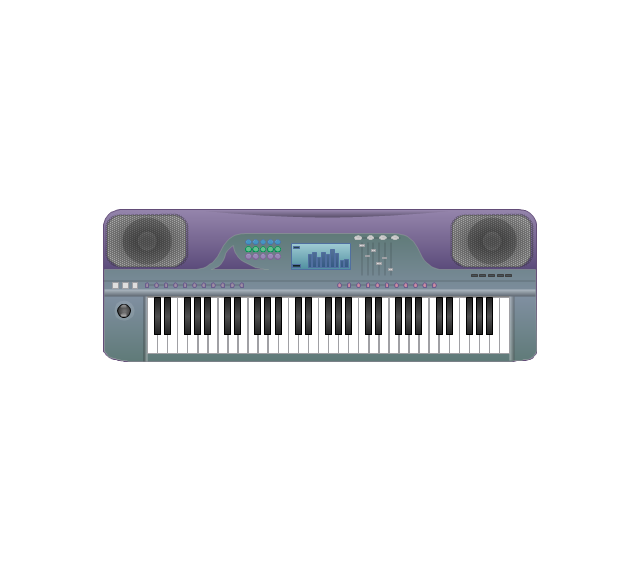
Synthesizer
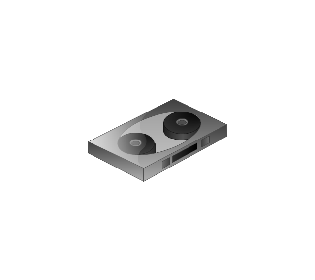
Compact Cassette
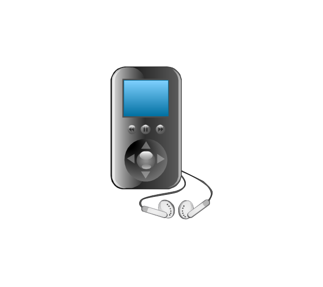
Mobile digital media player
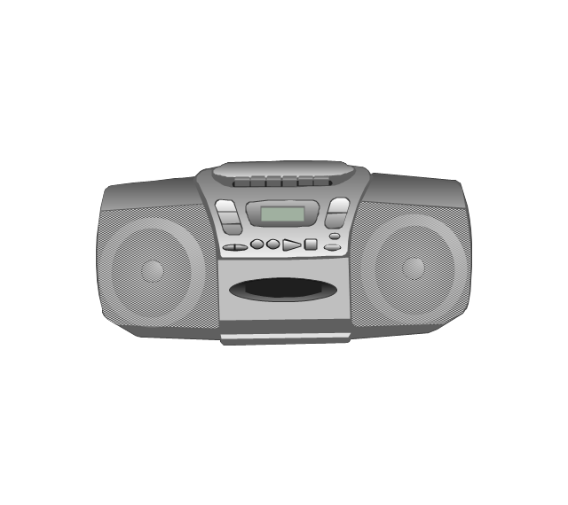
Boom Box
CD-player
Jazz

Pop

Rap

Techno

Rock

Trance

The vector stencils library "Telecommunication networks" contains 32 clipart images of telecommunication network devices and equipment for drawing telecom network diagrams.
"A telecommunications network is a collection of terminal nodes, links and any intermediate nodes which are connected so as to enable telecommunication between the terminals.
The transmission links connect the nodes together. The nodes use circuit switching, message switching or packet switching to pass the signal through the correct links and nodes to reach the correct destination terminal.
Each terminal in the network usually has a unique address so messages or connections can be routed to the correct recipients. The collection of addresses in the network is called the address space." [Telecommunications network. Wikipedia]
The clip art example "Telecommunication networks - Vector stencils library" was created using the ConceptDraw PRO diagramming and vector drawing software extended with the Telecommunication Network Diagrams solution from the Computer and Networks area of ConceptDraw Solution Park.
Internet

Globe

Base station

Satellite dish

Satellite dish

Communications satellite

Wireless cell tower

Radio waves

Radio waves

Cellular phone

Server

Laptop computer

Desktop computer

Car

Satellite truck

House

House

Office building

Mountain

Tree

Tree

User

Call-center

Multi-storey

Antenna

Router

IP phone

Fax

Network cell

IP Camera

Wireless router

Networking device

Cisco Routers. Cisco icons, shapes, stencils and symbols

Basic Flowchart Examples

How To Make an Effective PowerPoint Presentation

- Electrical Symbols — Transistors | Electrical Symbols ...
- Electrical Symbols — Switches and Relays | Electrical Symbols ...
- Electrical Symbols , Electrical Diagram Symbols | Electrical Symbols ...
- Electrical Symbols — Electron Tubes | Electrical Symbols ...
- Electrical Symbols — Semiconductor | Electrical Symbols , Electrical ...
- Electronic Component
- Electrical Symbols — Resistors | Electrical Symbols — Transmission ...
- Electrical Symbols — Transistors | Design elements - Transistors ...
- Electrical Symbols — Resistors | Design elements - Resistors ...
- Electrical Symbols , Electrical Diagram Symbols | Electrical Symbols ...
- Electrical Symbols , Electrical Diagram Symbols | Home Electrical ...
- Design elements - Electron tubes | Electrical Symbols , Electrical ...
- Electrical Symbols , Electrical Diagram Symbols | Electrical Symbols ...
- Draw Symbols Of Different Compound Used In Electric Circuit
- Design elements - Transistors | Design elements - MOSFET | Design ...
- Electrical Symbols — Integrated Circuit | Wiring Diagrams with ...
- Electrical Symbols — Resistors | Electrical Symbols — Transistors ...
- Electrical Symbols — VHF UHF SHF | Design elements - Transistors ...
- Electrical Symbols — MOSFET | Electrical Symbols — IGFET ...
- Electrical Symbols , Electrical Diagram Symbols | Electrical Symbols ...