Electrical Symbols — Stations
A power station is an industrial facility for the generation of electric power. Most power stations contain one or more generators, a rotating machine that converts mechanical power into electrical power. The relative motion between a magnetic field and a conductor creates an electrical current. The energy source harnessed to turn the generator varies widely. Most power stations in the world burn fossil fuels such as coal, oil, and natural gas to generate electricity. Others use nuclear power, but there is an increasing use of cleaner renewable sources such as solar, wind, wave and hydroelectric.
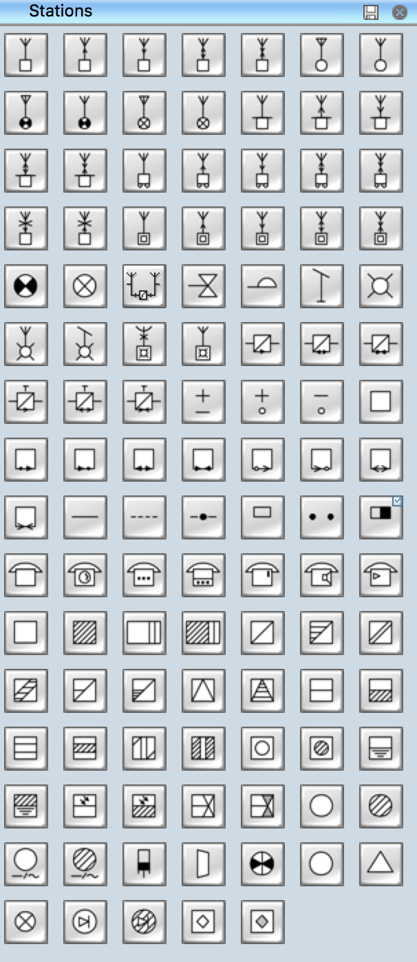
Pic. 1. Stations Library
ConceptDraw DIAGRAM is a powerful software for creating professional looking electrical diagram quick and easy. For this purpose you can use the Electrical Engineering solution from the "Engineering" area of ConceptDraw Solution Park.
Electrical Engineering Solution for ConceptDraw DIAGRAM provides the stencils libraries of ready-to-use predesigned 926 vector symbols, templates and samples that make your electrical drawing quick, easy and effective.
26 libraries of the Electrical Engineering Solution of ConceptDraw DIAGRAM make your electrical diagramming simple, efficient, and effective. You can simply and quickly drop the ready-to-use objects from libraries into your document to create the electrical diagram.
Pic. 2. Electrical Engineering symbols
Electrical diagram software will assist you in drawing your electrical diagrams with minimal effort and makes it very easy for beginners. Electrical symbols and smart connectors help present your electrical drawings, electrical schematic, wiring diagrams and blue prints.

Pic. 3. Electrical Symbols — Stations
Most of the electrical symbols can be changed in their appearance, styles and colors according to users' requirements. Electrical symbols are used to represent various electrical and electronic devices in a schematic diagram of an electrical or electronic circuit.
The following table lists some stations electrical symbols in our electrical diagram software.
Symbol | Meaning | |
Electrical Symbols — Stations | ||
![]() | Radio station | |
![]() | Transmission radio station | |
![]() | Reception radio station | |
![]() | Alternating radio station | |
![]() | Simultaneous radio station | |
![]() | General radio station | |
![]() | General radio station 2 | |
![]() | End radio station | |
![]() | End radio station 2 | |
![]() | Repeater radio station | |
![]() | Repeater radio station 2 | |
![]() | Portable station | |
![]() | Transmission portable station | |
![]() | Reception portable station | |
![]() | Alternating portable station | |
![]() | Simultaneous portable station | |
![]() | Mobile station | |
![]() | Mobile transmission station | |
![]() | Mobile reception station | |
![]() | Mobile alternating station | |
![]() | Mobile simultaneous station | |
![]() | Direction finding station | |
![]() | Radio beacon station | |
![]() | Controlling station | |
![]() | Transmission controlling station | |
![]() | Reception controlling station | |
![]() | Alternating controlling station | |
![]() | Simultaneous controlling station | |
![]() | End station | |
![]() | Repeater station | |
![]() | Radio relay station | |
![]() | Subscriber equipment | |
![]() | Subscriber equipment 2 | |
![]() | Passive relay | |
![]() | Space station | |
![]() | Active space station | |
![]() | Passive space station | |
![]() | Earth tracking station | |
![]() | Earth communication service | |
![]() | Telegraph repeater, one-way simplex | |
![]() | Telegraph repeater, two-way simplex | |
![]() | Telegraph repeater, duplex | |
![]() | Telegraph repeater, one-way simplex 2 | |
![]() | Telegraph repeater, two-way simplex 2 | |
![]() | Telegraph repeater, duplex 2 | |
![]() | Telegraph repeater qualifiers, polar direct-current (double current) | |
![]() | Telegraph repeater qualifier, neutral direct-current (single current) +/o | |
![]() | Telegraph repeater qualifier, neutral direct-current (single current) -/o | |
![]() | Telegraph equipment | |
![]() | Telegraph transmitter | |
![]() | Telegraph receiver | |
![]() | Two-way simplex telegraph | |
![]() | Duplex telegraph | |
![]() | Telegraph transmitter 2 | |
![]() | Telegraph receiver 2 | |
![]() | Two-way simplex telegraph 2 | |
![]() | Duplex telegraph 2 | |
![]() | Telegraph equipment qualifier, tape printing | |
![]() | Telegraph equipment qualifier, tape perforating | |
![]() | Telegraph equipment qualifier, tape printing/perforating | |
![]() | Telegraph equipment qualifier, page printing | |
![]() | Telegraph equipment qualifier, keyboard | |
![]() | Telegraph equipment qualifier, facsimile | |
![]() | Telephone | |
![]() | Dial telephone | |
![]() | Push-button telephone | |
![]() | Multiple lines telephone | |
![]() | Coin box telephone | |
![]() | Speaker phone | |
![]() | Amplified phone | |
![]() | Generating station (planned) | |
![]() | Generating station (in service) | |
![]() | Electric heat station (planned) | |
![]() | Electric heat station (in service) | |
![]() | Hydroelectric station (planned) | |
![]() | Hydroelectric station (in service) | |
![]() | Hydroelectric station (planned) 2 | |
![]() | Hydroelectric station (in service) 2 | |
![]() | Hydroelectric station (planned) 3 | |
![]() | Hydroelectric station (in service) 3 | |
![]() | Hydroelectric station (planned) 4 | |
![]() | Hydroelectric station (in service) 4 | |
![]() | Thermoelectric station (planned) | |
![]() | Thermoelectric station (in service) | |
![]() | Coal fueled station (planned) | |
![]() | Coal fueled station (in service) | |
![]() | Oil/gas fueled station (planned) | |
![]() | Oil/gas fueled station (in service) | |
![]() | Nuclear station (planned) | |
![]() | Nuclear station (in service) | |
![]() | Geothermic station (planned) | |
![]() | Geothermic station (in service) | |
![]() | Solar station (planned) | |
![]() | Solar station (in service) | |
![]() | Wind station (planned) | |
![]() | Wind station (in service) | |
![]() | Substation (planned) | |
![]() | Substation (in service) | |
![]() | Converting substation (planned) | |
![]() | Converting substation (in service) | |
![]() | Prime mover, reciprocating engine | |
![]() | Prime mover, gas turbine | |
![]() | Converting station | |
![]() | Converting station 2 | |
![]() | Switching station | |
![]() | Switching station 2 | |
![]() | Rectifier substation (planned) | |
![]() | Rectifier substation (in service) | |
![]() | Plasma station MHD (planned) | |
![]() | Plasma station MHD (in service) |
In electronics and telecommunications a transmitter or radio transmitter is an electronic device which, with the aid of an antenna, produces radio waves. The transmitter itself generates a radio frequency alternating current, which is applied to the antenna. When excited by this alternating current, the antenna radiates radio waves.
How to Create an Electrical Diagram Using Stations Library
- Open ConceptDraw DIAGRAM new document page.
- Select libraries from Electrical Engineering section.
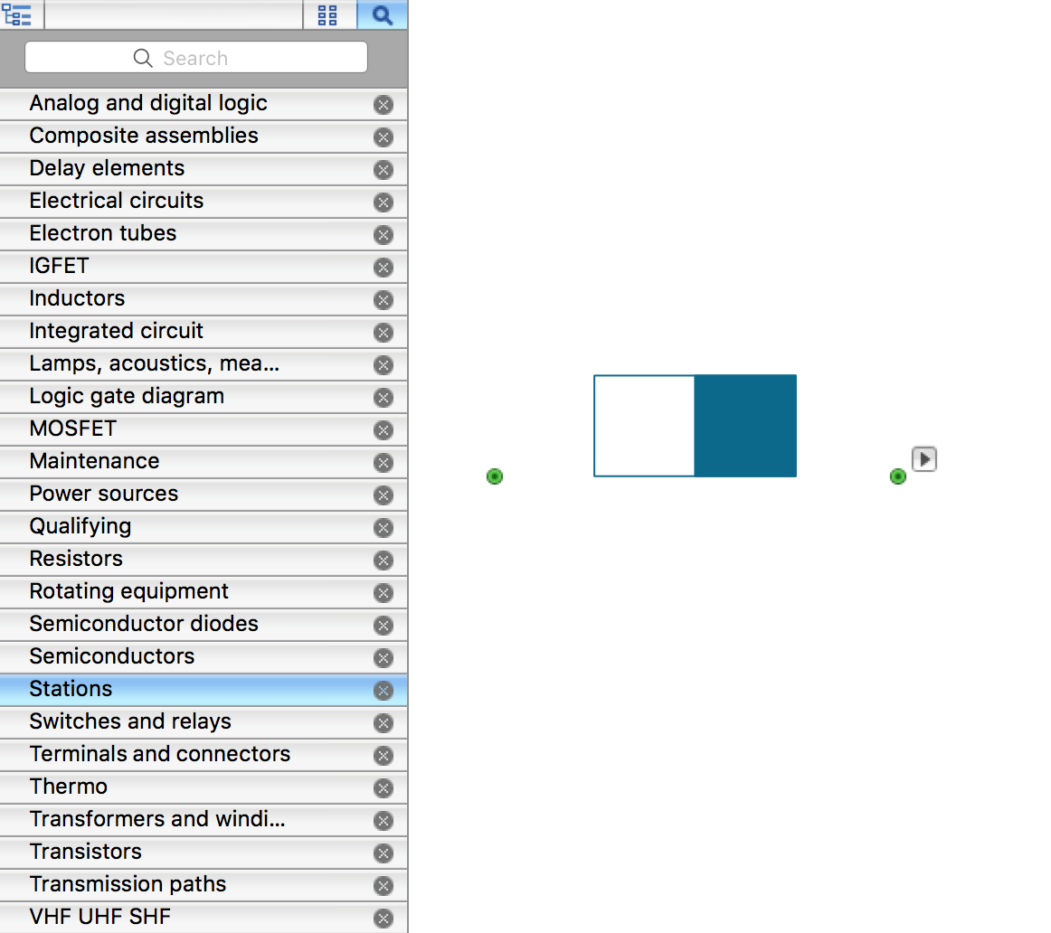
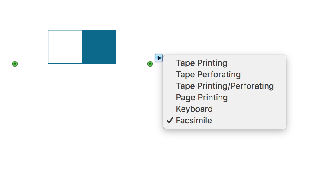
- Stations library contains objects, identified by a blue tile in the library pane. Such objects can be edited by using the Action button menu. To open the menu select an object and click the
button in the upper right corner of the object.
- Select the Smart Connector tool
. To connect elements using this tool, drag the connector from one connect dot to another.You can use Layers to place connections on different layers.
TEN RELATED HOW TO's:
Electrical Symbols — Lamps, Acoustics, Readouts →
Wiring and circuit diagrams use special symbols recognized by everyone who uses the drawings. The symbols on the drawings show how components like resistors, capacitors, inductors, switches, lamps, acoustic devices, measuring devices and other electrical and electronic components are connected together. 26 libraries of the Electrical Engineering Solution of ConceptDraw DIAGRAM make your electrical diagramming simple, efficient, and effective. You can simply and quickly drop the ready-to-use objects from libraries into your document to create the electrical diagram.
Flowchart design. Flowchart symbols, shapes, stencils and icons →
When thinking about data visualization, one of the first tools that comes to mind is a flowchart design. You can find flowchart symbols, shapes, stencils and icons easily on the Internet, but it might take time to systematize this information. Nevertheless, once you start flowcharting, you’ll love its simplicity and efficiency. This diagram consists from standard flowchart symbols, approved by ANSI (American National Standard Institute) for drawing flowcharts. A flowchart is a diagram that represents a step-by-step algorithm of any process, displaying the process stages as boxes that are connected with arrows. Flowchart design makes it clear and readable. Flowchart designed using ConceptDraw DIAGRAM flowchart software allows to make attractive and clear process presentation, it makes interpretation of the business process flow fresh and versatile. Great flowchart design view is a big advantage over the diagram created manually on a paper.
Cisco Network Design. Cisco icons, shapes, stencils, symbols and design elements →
Talking about companies, that have influenced the entire industry, we should mention Cisco and it’s influence on network design. Nowadays, this equipment has became a kind of standard, and Cisco icons, shapes, stencils, symbols and design elements are easily recognized among others. You can use these icons to develop a network diagram of any complexity. When dealing with creating a pack of network documentation, system administrator often have to depict a network containing a network equipment of such a well-known manufacturer as Cisco. As Cisco has developed its own production standard icons that are strongly recommended to use in Cisco network diagrams. The best way to draw Cisco Network diagram Cisco certified icons is using ConceptDraw solution for Cisco Network Diagrams. Using Cisco symbols library provided by this solution allows system administrator, or network architect to design a prototype of a new network or document an existing one.
Network Glossary Definition →
When talking about engineering, one should define all the terms used, so anybody could understand the topic. Typical network glossary contains definitions of numerous network appliances, types of networks and cable systems. The understanding of basic is crucial for server management, network administration and investigating problems. The network glossary defines terms related to networking and communications. The most of glossary items has their visual representation in ConceptDraw DIAGRAM libraries of the Computer Network Diagrams solution. This illustration presents a local area network (LAN) diagram. It designed to show the way the interaction of network devices in a local network. The diagram uses a library containing symbols of network equipment, connections and the end-point devices such as network printer, hubs, server, modem and finally computers (PC, mac, laptop). This diagram depicts a physical LAN topology.
How To use House Electrical Plan Software →
Electrical plan is a document that is developed during the first stage of the building design. This scheme is composed of conventional images or symbols of components that operate by means of electric energy. To simplify the creation of these schemes you can use house electrical plan software, which will not require a long additional training to understand how to use it. You only need to install the necessary software ant it’s libraries and you’ll have one less problem during the building projection. Any building contains a number of electrical systems, including switches, fixtures, outlets and other lightening equipment. All these should be depicted in a building electrical plans and included to general building documentation. This home electrical plan displays electrical and telecommunication devices placed to a home floor plan. On the plan, each electrical device is referenced with the proper symbol. Electrical symbols are used for universal recognition of the building plan by different persons who will be working on the construction. Not all possible electric symbols used on a certain plan, so the symbols used in the current home plan are included to a legend. The electrical home plan may be added as a separate document to a complete set of building plans.
Electrical Symbols — Transformers and Windings →
A transformer is an electrical device that transfers electrical energy between two or more circuits through electromagnetic induction. Electromagnetic induction produces an electromotive force within a conductor which is exposed to time varying magnetic fields. Transformers are used to increase or decrease the alternating voltages in electric power applications. 26 libraries of the Electrical Engineering Solution of ConceptDraw DIAGRAM make your electrical diagramming simple, efficient, and effective. You can simply and quickly drop the ready-to-use objects from libraries into your document to create the electrical diagram.
Cisco Network Topology. Cisco icons, shapes, stencils and symbols →
In general, you can use any icons to represent network equipment on a diagram. However, there are some icons, for instance, Cisco icons, shapes, stencils and symbols, that are recognizable worldwide. Using those icons you can create Cisco network topology diagrams in minutes and share them anywhere. The icons depicting Cisco network equipment are recognized and generally applied as standard images for designing network diagrams. They are free to used , but can not be reworked. Cisco network diagrams are created to depict how signals processed on the network equipment and end-user computers and how data transfer through LAN or WLAN between nodes. The vector graphic library of ConceptDraw CISCO Network Diagrams solution includes about 90 icons of Cisco network equipment for designing computer network diagrams with ConceptDraw DIAGRAM.
Mesh Network Topology Diagram →
The reliability is a cornerstone for any corporate computer network. If you want to provide a high fault tolerance, a mesh network topology would be the solution. The main advantage of this network is that every node can work as a commutator, although it’s not easy to set up this kind of network. A mesh network topology may be full, or partial. Full mesh network means that each node of the network (computer, workstation or other equipment) is connected directly to each of the other nodes. A partial mesh topology means that a part of nodes are connected with a whole network, and the other part of nodes are only connected to those equipment, they exchange the majority of data. This illustration shows schematic diagram of a partial mesh network containing six nodes. Each node is represented as a circles and connections are drawn as straight lines. The connections may be both wired and wireless. This scheme can be used to make the specific logical or physical network diagrams by means the ConceptDraw Computer and Networks solution.
Electrical Symbols — Terminals and Connectors →
An electrical connector, is an electro-mechanical device used to join electrical terminations and create an electrical circuit. Electrical connectors consist of plugs (male-ended) and jacks (female-ended). The connection may be temporary, as for portable equipment, require a tool for assembly and removal, or serve as a permanent electrical joint between two wires or devices. 26 libraries of the Electrical Engineering Solution of ConceptDraw DIAGRAM make your electrical diagramming simple, efficient, and effective. You can simply and quickly drop the ready-to-use objects from libraries into your document to create the electrical diagram.
Home Electrical Plan →
Planning and construction of any building begins from the designing its floor plan and a set of electrical, telecom, piping, ceiling plans, etc. Solutions of Building Plans Area of ConceptDraw Solution Park can effectively help you develop all these plans. Let's design the Home Electrical Plan in ConceptDraw DIAGRAM quick and easy.