ConceptDraw DIAGRAM Compatibility with MS Visio

HelpDesk
How to Open MS Visio® 2013/2016 Files on a Mac®
Network Diagram Software. LAN Network Diagrams. Physical Office Network Diagrams


Is ConceptDraw DIAGRAM an Alternative to Microsoft Visio?
UML Diagram Visio

Using the 13 libraries of the Rapid UML Solution for ConceptDraw DIAGRAM you can create your own visual vector UML diagrams quick and easy.
HelpDesk
How To Create Cause and Effect (Fishbone) Diagram in MS Visio
 Diagram in MS Visio")
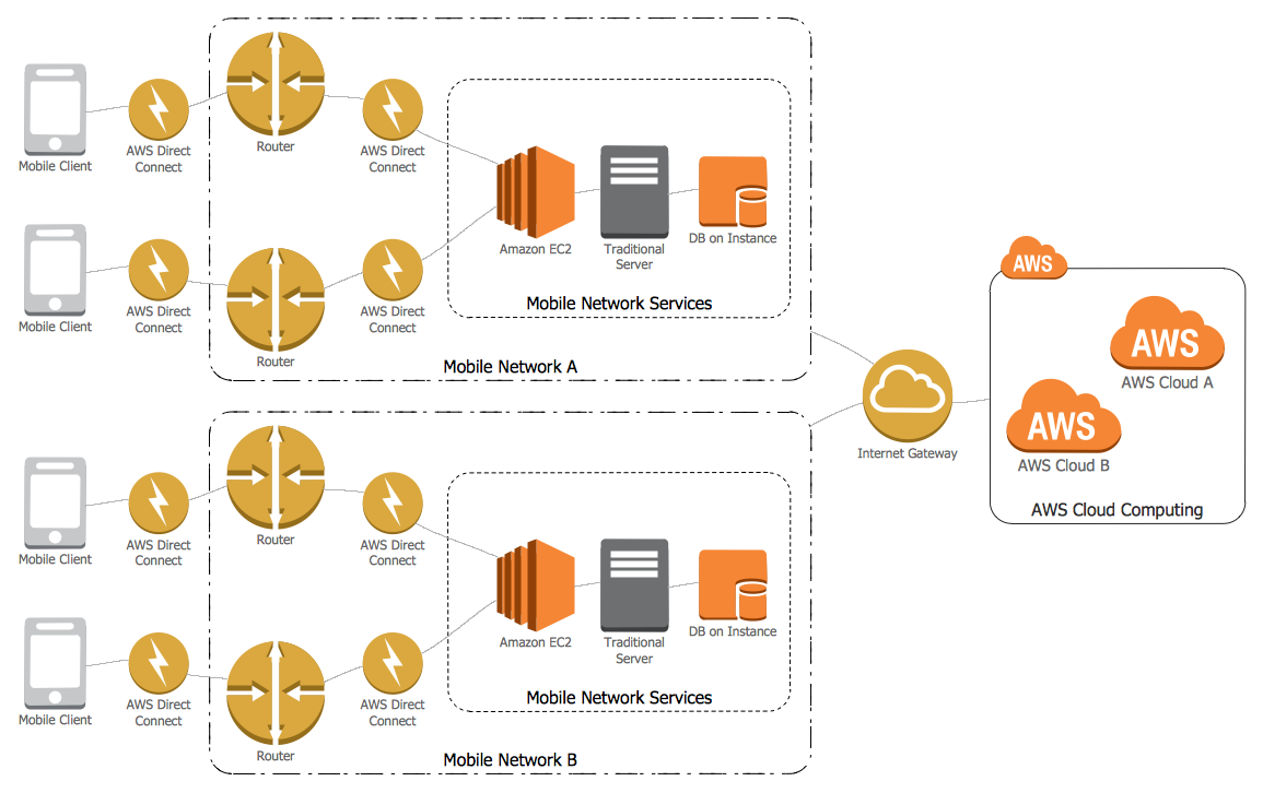
Amazon Web Services Diagrams diagramming tool for architecture

Model Based Systems Engineering

Map Directions

HelpDesk
How to Create a Timeline Diagram

ConceptDraw DIAGRAM : Able to Leap Tall Buildings in a Single Bound
Amazon Cloud
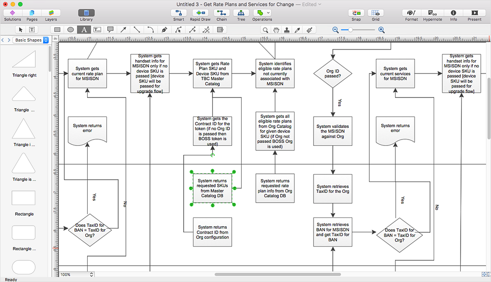
Flowchart Software

ConceptDraw DIAGRAM flowchart software will help to quickly create new flowcharts, workflow, NS Diagram, BPMN Diagram, Cross-functional flowcharts, data flow diagrams and highlight flowcharts.
Feature-rich flowchart maker, free thousand flowchart examples and templates and colored symbols that will allow you to create professional looking flowcharts simply.
ConceptDraw DIAGRAM supports macOS and Windows.

Entity Relationship Diagram - ERD - Software for Design Crows Foot ER Diagrams
_Win_Mac.png)

Functional Block Diagram

- Edit Visio Online
- Online Microsoft Visio Editor
- Online Ms Visio Editor
- Free Online Visio Editor
- Visio Online Editor
- Microsoft Visio Online
- Microsoft Visio Online Editor
- Ms Visio Online Editor
- In searching of alternative to MS Visio for MAC and PC with ...
- Online Visio Editor Free
- IDEF0 Visio | In searching of alternative to MS Visio for MAC and PC ...
- Flowchart Software | In searching of alternative to MS Visio for MAC ...
- How to Open MS Visio ® 2013/2016 Files on a Mac® Using ...
- Diagram Viewer Online Help | Visio Files and ConceptDraw | How to ...
- How to Open MS Visio ® 2013/2016 Files on a Mac® Using ...
- Visio Like Online
- ConceptDraw PRO Compatibility with MS Visio | How to Open MS ...
- ConceptDraw Solution Park | Diagram Viewer Online Help | How to ...
- Office Online Visio
- Edit Visio Files Online
- ERD | Entity Relationship Diagrams, ERD Software for Mac and Win
- Flowchart | Basic Flowchart Symbols and Meaning
- Flowchart | Flowchart Design - Symbols, Shapes, Stencils and Icons
- Flowchart | Flow Chart Symbols
- Electrical | Electrical Drawing - Wiring and Circuits Schematics
- Flowchart | Common Flowchart Symbols
- Flowchart | Common Flowchart Symbols