Amazon Web Services Diagrams
diagramming tool for architecture
The AWS Architecture Diagrams solution includes icons, sample and templates for several Amazon Web Services products and resources, to be used when creating architecture diagrams. The icons are designed to be simple so that you can easily incorporate them in your diagrams and put them in your whitepapers, presentations, datasheets, posters or any technical material you like.
For IT specialists, system designers and network administrators, the AWS Architecture Diagrams solution offers a wide range of recognizable graphic icons to help illustrate a diagram, as well as a helpful selection of templates and samples to model a design on. Architecture diagrams are a great way to communicate your design, deployment and topology. Here you will find an official collection of AWS resources that will help you build great AWS Architecture diagrams.
"The AWS Architecture Center is designed to provide you with the necessary guidance and application architecture best practices to build highly scalable and reliable applications in the AWS cloud. These resources will help you understand the AWS platform, its services and features, and will provide architectural guidance for design and implementation of systems that run on the AWS infrastructure."
ConceptDraw - Diagramming Tool for:
- Create Web Application Architecture
- Architect infrastructure based on AWS® (Amazon Web Services)
- Design application services based on AWS® (Amazon Web Services)
- Design auto-scalable architecture
- Design for elastic compute cloud
- Create Amazon Web Services planning diagrams
- Illustrate whitepapers and presentations
- Create vector graphics files
 This diagram was created in ConceptDraw® PRO using the AWS® Architecture Diagram library from the Amazon Web Services Architecture Diagrams solution (AWS solution).
See also:
-
Diagramming software for Amazon Web Service
Diagrams, charts, schemes, symbols and icons -
AWS Simple Icons for Architecture Diagrams
Diagramming for Amazon Web Services architecture - Design Elements and Icons - Samples
Network Diagrams — AWS Architecture
TEN RELATED HOW TO's:The Time-Money-Quality Triangle illustrates an advertising truism, that you can't have all three. Picture: Pyramid DiagramRelated Solutions:The behavior of worker in organization is influences organizational effectiveness. A simple block diagram made with ConceptDraw Block diagrams solution can improve the understanding of expectations of workers regarding what they l contribute to organization and what they wait to obtain. Making block diagram depicting the individual behavior in organization is used in HR management to obtain an optimal and positive overall contribution to the organization. The behavior of worker in organization is influences organizational effectiveness. A simple block diagram made with ConceptDraw Block diagrams solution can improve the understanding of expectations of workers regarding what they l contribute to organization and what they wait to obtain. Making block diagram depicting the individual behavior in organization is used in HR management to obtain an optimal and positive overall contribution to the organization.
 Picture: Basic DiagrammingRelated Solution:ConceptDraw DIAGRAM is perfect for software designers and software developers who need to draw Network Layout Diagrams.
.png) Picture: Design Element: Network Layoutfor Network DiagramsThere are many ways to describe a database structure. One of the most usual is to draw an entity relationship diagram (ERD) using a Crow’s Foot notation to represent database elements. If you don’t want to draw it on paper, you should use an appropriate software. An entity-relationship (ER) diagram is used to show the structure of a business database. ERD represents data as objects (entities) that are connected with standard relationships symbols which Illustrate an association between entities. ERD, there is a wide range of ERD notations used by data bases architects for reflecting the relationships between the data entities. According to the crow’s foot notation relationships are drawn as single labeled lines designating a certain kinds of relationship. Crow foot notation is a most frequently used ERD standard, because of improved readability of diagrams, with a more accurate use of space on the page.
Picture: Design Element: Network Layoutfor Network DiagramsThere are many ways to describe a database structure. One of the most usual is to draw an entity relationship diagram (ERD) using a Crow’s Foot notation to represent database elements. If you don’t want to draw it on paper, you should use an appropriate software. An entity-relationship (ER) diagram is used to show the structure of a business database. ERD represents data as objects (entities) that are connected with standard relationships symbols which Illustrate an association between entities. ERD, there is a wide range of ERD notations used by data bases architects for reflecting the relationships between the data entities. According to the crow’s foot notation relationships are drawn as single labeled lines designating a certain kinds of relationship. Crow foot notation is a most frequently used ERD standard, because of improved readability of diagrams, with a more accurate use of space on the page._Win_Mac.png) Picture: Entity Relationship Diagram - ERD - Software for Design Crows Foot ER DiagramsRelated Solution:The network architecture and design specialization will help you gain the technical leadership skills you need to design and implement high-quality networks that support business needs.
Picture: Entity Relationship Diagram - ERD - Software for Design Crows Foot ER DiagramsRelated Solution:The network architecture and design specialization will help you gain the technical leadership skills you need to design and implement high-quality networks that support business needs. Picture: Computer Network Architecture. Computer and Network ExamplesAny business process consists from a number of tasks carrying out the certain business goal. It is useful to diagram business processes to ensure that they are as foolproof, logical and sequential as possible. This business process diagram describes a typical booking process flow by the example of a cab booking process. It can be used as a roadmap for any booking system implementation. Diagramming a business process allows you to look at the entire project and take into account all types of possible scenarios. Business process diagram helps you investigate and clarify the process thoroughly so that you can find out how it can be improved. Business process diagram supports team communications by ensuring that each process element is clear and everyone in the team is on the same page. Sometimes your company brings you less profit than you expect it to be, and it’s difficult to reveal the causes. Maybe it’s time to learn new technologies, because business diagram are easily developed by means of special software, so you won’t make any extra effort. In return, you will increase your productivity and get more done in a less time.
 Picture: Business Diagram SoftwareRelated Solutions:UML Component Diagram Online Shopping. This sample was created in ConceptDraw DIAGRAM diagramming and vector drawing software using the UML Component Diagram library of the Rapid UML Solution from the Software Development area of ConceptDraw Solution Park. This sample shows the concept of the online shopping and is used for the understanding of the online shopping processes, of the online shops working processes, for projection and creating of the online stores.
 Picture: UML Component Diagram Example - Online ShoppingRelated Solution:This sample was created in ConceptDraw DIAGRAM diagramming and vector drawing software using the Flowcharts solution from the Diagrams area of ConceptDraw Solution Park. This sample shows the Flowchart that displays the procedures of 2PP (two-party preferred) voting and counting the voters. The two-party-preferred vote is the result of the elections that was distributed to the final two parties.
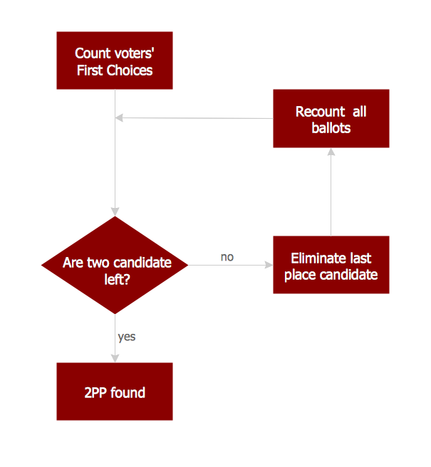 Picture: Basic Flowchart Images. Flowchart ExamplesRelated Solution:The best way to visualize the introduction to Cloud computing architecture is to create diagrams and schematics representing what is a cloud computing and how it works. For their design, we recommend to use a powerful ConceptDraw DIAGRAM diagramming and vector drawing software supplied with Cloud Computing Diagrams solution from the Computers and Network area of ConceptDraw Solution Park
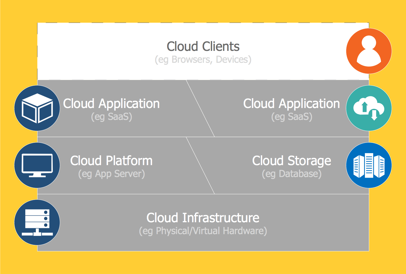 Picture: Introduction to Cloud Computing ArchitectureRelated Solution:In general, you can use any icons to represent network equipment on a diagram. However, there are some icons, for instance, Cisco icons, shapes, stencils and symbols, that are recognizable worldwide. Using those icons you can create Cisco network topology diagrams in minutes and share them anywhere. The icons depicting Cisco network equipment are recognized and generally applied as standard images for designing network diagrams. They are free to used , but can not be reworked. Cisco network diagrams are created to depict how signals processed on the network equipment and end-user computers and how data transfer through LAN or WLAN between nodes. The vector graphic library of ConceptDraw CISCO Network Diagrams solution includes about 90 icons of Cisco network equipment for designing computer network diagrams with ConceptDraw DIAGRAM.
 Picture: Cisco Network Topology. Cisco icons, shapes, stencils and symbolsRelated Solution:ConceptDrawDIAGRAM 18