Made with
ConceptDraw
DIAGRAM 18

Is ConceptDraw DIAGRAM an Alternative to Microsoft Visio?

by Holger Maassen: www.blogspot.com www.iama.de

I had been asked whether ConceptDraw is an alternative to Visio — I strongly believe YES. ConceptDraw is a useful diagram software that enables you to create sketches of functions, diagram and so on to visualize information and processes cost — and effort effectively.

It provides a comprehensive set of features and tools to effortlessly represent and share any kind of concept, wireframe or structure on a smooth and easy way.

It offers a set of vector drawing tools that can compete with any professional illustration program including Visio. Customizable grid and snap tool as well as the options to align shapes help to position your shapes precisely without a doubt better than Visio. Unlimited number of layers are supported — and these layers are easy to handle — it`s very similar to FreeHand — not as complicated as Visio — when I work with Visio I use the layers feature hardly ever, because it’s not user friendly.

Lines stay linked to their shapes, so you don’t need to redraw your diagram every time you move something. Smart connectors can flow shapes around, display gaps or bridges where they cross other connectors. Really every shape can be turned into a shape with connectors. The automatic connection mode is also available. You can easily add connection points to any part of shapes or if needed to lines.

Like Visio ConceptDraw goes with dozens of collections of shapes, but the utility is almost the same too — you have to create your own customized shapes. This is the next feature which is more user friendly than I know it of Visio.

Most of shapes are able to contain text. ConceptDraw offers extensive formatting capabilities, and various tools for work with text, such as adding text to a shape, editing shape’s text and text searching, replacing, formatting and repositioning, adjusting shape’s size to fit its text and text auto-expand mode, choosing size, color and font of text; alignment, margins and text background color.

All these features are almost the same like Visio apart from tabs.

Is ConceptDraw an Alternative to Visio

Figure 1: MS Visio Document

Quick-and-easy access to main tools and settings with customizable toolbars and floating dialogs. Concept Draw adheres to the What-You-See-Is-What-You-Get wysiwyg-principle and features anti-aliasing that brings your diagramming to a new level of presentation quality.

I can give custom assets to every shape, add user defined context menus, and create links to other shapes, files or programs. ConceptDraw Basic scripts can be associated with shapes, providing virtually unlimited control over them.Concept Draw allows import and export files to a large number of raster, vector, multimedia and text formats, making it easy to exchange data with other applications.

As far as I know Concept Draw is the only professional diagramming software that works on both Windows and Macintosh platforms.

All its documents and libraries are absolutely compatible and can be exchanged comfortable between the platforms.As a freelancer I’ve worked always on both systems Mac and PC parallel — during the day with PC at the offices of my clients and with Mac in the evenings and during the weekends at home.

But also in many agencies I saw both systems. Personally I prefer and I love Mac.

Is ConceptDraw DIAGRAM an Alternative to Microsoft Visio? *

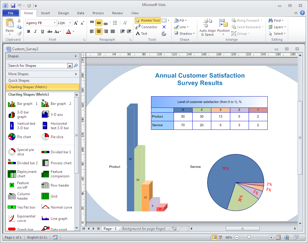
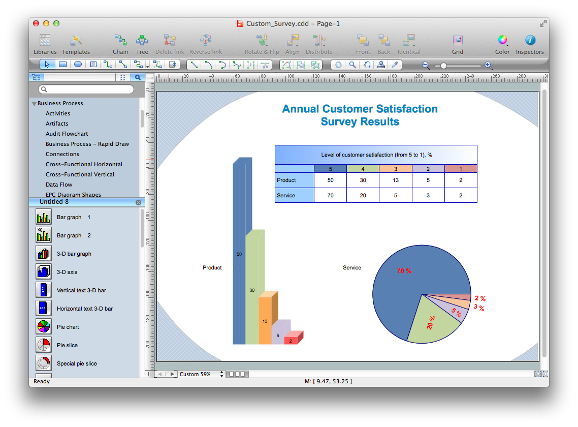
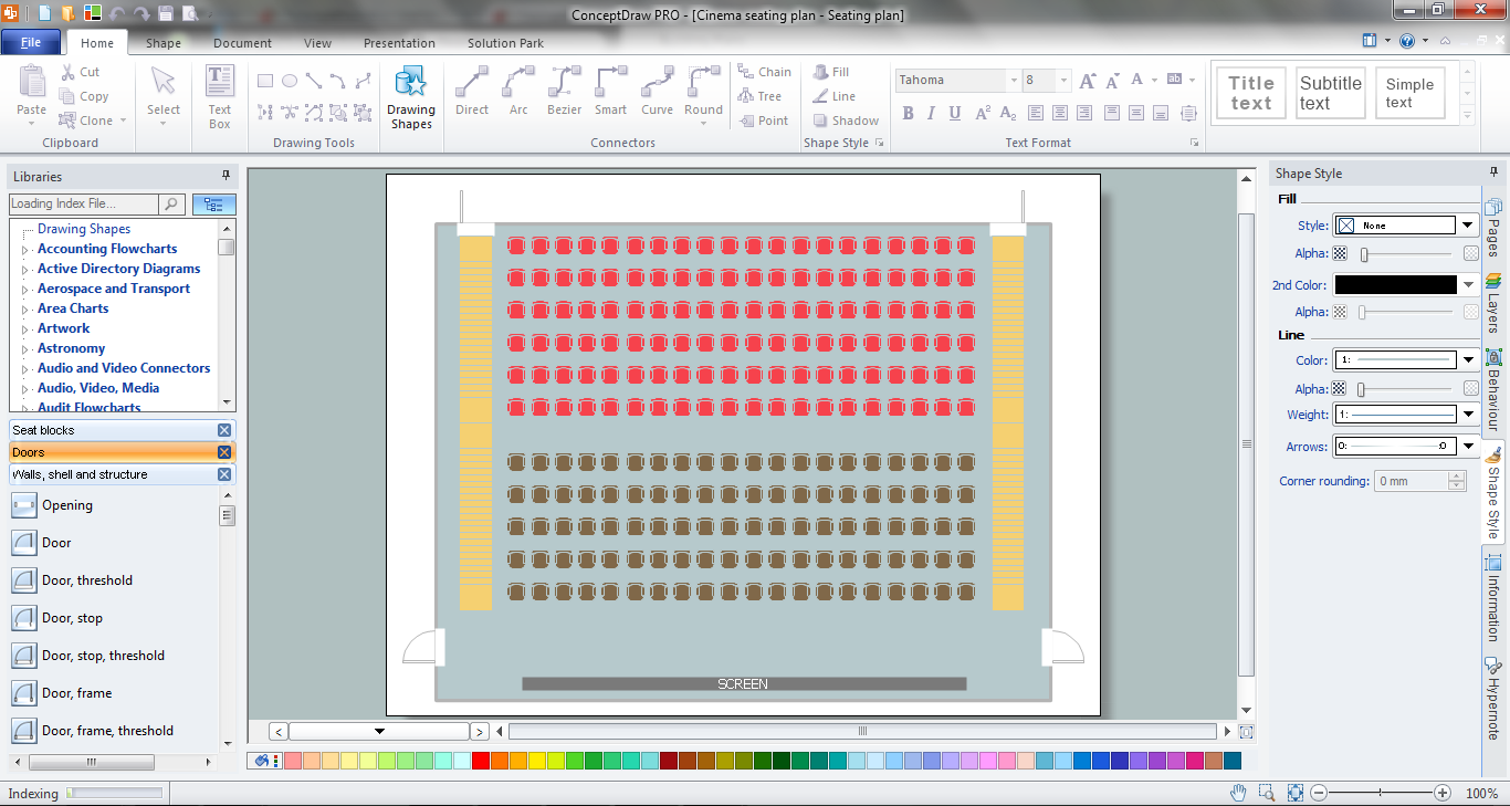
Figure 2: ConceptDraw DIAGRAM Document


(I work with Mac since 1985 — I bought my first own PC two years ago). I never recognized any significant or considerable differences between Mac and PC concerning the features.

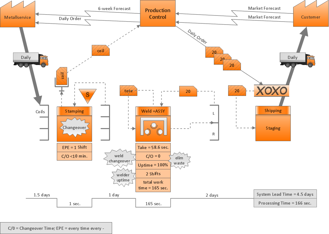
Normally I have a preference for Mac … but on the PC the Concept Draw interface is smaller and more “compact”. Generally I start with mind mapping before I build up flowcharts and wire frames or the story boarding. It is very important to me to stays in time and budget. I need a tool to plan and control the timeline and efforts. And for this Odessa offers a useful set of software.

MS Visio 2016 converted into ConceptDraw DIAGRAM title=

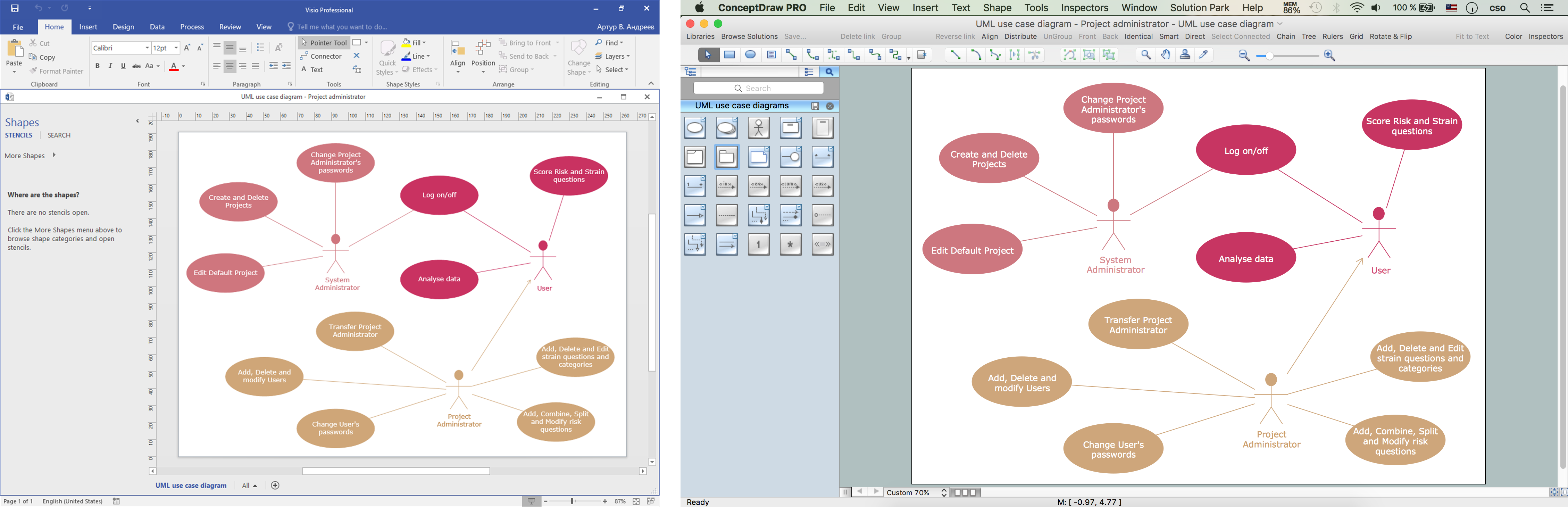
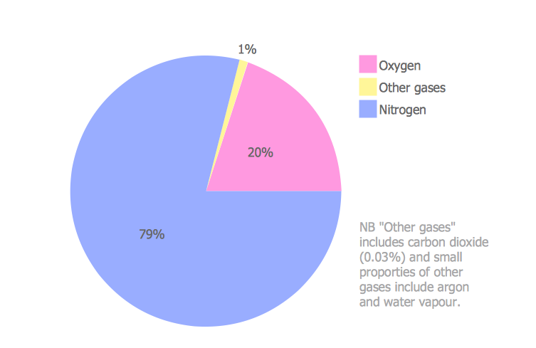
Figure 3: MS Visio 2016 diagram (VSDX file format) has been converted into ConceptDraw DIAGRAM diagram.

MS Visio for Mac and Windows — ConceptDraw as an alternative to MS Visio.
ConceptDraw DIAGRAM delivers full-functioned alternative to MS Visio. ConceptDraw DIAGRAM supports import of Visio files. ConceptDraw DIAGRAM supports flowcharting, swimlane, orgchart, project chart, mind map, decision tree, cause and effect, charts and graphs, and many other diagram types.


TEN RELATED HOW TO's:
ConceptDraw DIAGRAM diagramming and vector drawing software extended with Physics solution from the Science and Education area is a powerful software for creating various physics diagrams. Physics solution provides all tools that you can need for physics diagrams designing. It includes 3 libraries with predesigned vector physics symbols: Optics Library, Mechanics Library and Nuclear Physics Library.Physics Symbols
Picture: Physics Symbols
Related Solution:
ConceptDraw Office is the most effective tool for planning, tracking, and reporting all types of projects with strong management capabilities, user friendly functionality, and superior ease of use. In this tutorial video we will assist you in planning and managing a project using ConceptDraw Office.How To Plan and Implement Projects Faster *
Picture: How To Plan and Implement Projects Faster
When trying to figure out the nature of the problems occurring within a project, there are many ways to develop such understanding. One of the most common ways to document processes for further improvement is to draw a process flowchart, which depicts the activities of the process arranged in sequential order — this is business process management. ConceptDraw DIAGRAM is business process mapping software with impressive range of productivity features for business process management and classic project management. This business process management software is helpful for many purposes from different payment processes, or manufacturing processes to chemical processes. Business process mapping flowcharts helps clarify the actual workflow of different people engaged in the same process. This samples were made with ConceptDraw DIAGRAM — business process mapping software for flowcharting and used as classic visio alternative because its briefly named "visio for mac" and for windows, this sort of software named the business process management tools. This flowchart diagram shows a process flow of project management. The diagram that is presented here depicts the project life cycle that is basic for the most of project management methods. Breaking a project into phases allows to track it in the proper manner. Through separation on phases, the total workflow of a project is divided into some foreseeable components, thus making it easier to follow the project status. A project life cycle commonly includes: initiation, definition, design, development and implementation phases. Distinguished method to show parallel and interdependent processes, as well as project life cycle relationships. A flowchart diagram is often used as visual guide to project. For instance, it used by marketing project management software for visualizing stages of marketing activities or as project management workflow tools. Created with ConceptDraw DIAGRAM — business process mapping software which is flowcharting visio alternative or shortly its visio for mac, this sort of software platform often named the business process management tools.Process Flowchart
Picture: Process Flowchart: A Step-by-Step Comprehensive Guide
Related Solution:
While creating flowcharts and process flow diagrams, you should use special objects to define different statements, so anyone aware of flowcharts can get your scheme right. There is a short and an extended list of basic flowchart symbols and their meaning. Basic flowchart symbols include terminator objects, rectangles for describing steps of a process, diamonds representing appearing conditions and questions and parallelograms to show incoming data. This diagram gives a general review of the standard symbols that are used when creating flowcharts and process flow diagrams. The practice of using a set of standard flowchart symbols was admitted in order to make flowcharts and other process flow diagrams created by any person properly understandable by other people. The flowchart symbols depict different kinds of actions and phases in a process. The sequence of the actions, and the relationships between them are shown by special lines and arrows. There are a large number of flowchart symbols. Which of them can be used in the particular diagram depends on its type. For instance, some symbols used in data flow diagrams usually are not used in the process flowcharts. Business process system use exactly these flowchart symbols.Flowchart example showing a customer request approval process with start, input output, process steps, decision branches, and end
Picture: Flowchart Symbols: Meaning and Examples
Related Solution:
This sample was created in ConceptDraw DIAGRAM diagramming and vector drawing software using the UML Deployment Diagram library of the Rapid UML Solution from the Software Development area of ConceptDraw Solution Park. This sample shows the work of the ATM (Automated Teller Machine) banking system that is used for service and performing of the banking transactions using ATMs. System engineers can use comprehensive UML diagrams solution.UML Deployment Diagram Example - ATM System<br>UML diagrams *
Picture: UML Deployment Diagram Example - ATM SystemUML diagrams
Related Solution:
The VMware vNetwork Distributed Switch (vDS) is the new virtual switch (vSwitch) with vSphere 4 that extends the set of features of the VMware vNetwork Standard Switch (vSS). The VMware vSS is the base-level virtual networking alternative that extends the capabilities, configuration and appearance of the standard vSwitch in VMware ESX 3.5 to ESX 4.0 and vSphere 4. This example was created in ConceptDraw DIAGRAM using the Computer and Networks Area of ConceptDraw Solution Park and shows the VMware vDS network diagram.VMware vNetwork Distributied Switch (vDS).<br> Computer and Network Examples *
Picture: VMware vNetwork Distributied Switch (vDS). Computer and Network Examples
Related Solution:
Once you have created your document in ConceptDraw DIAGRAM and you want to share it with your colleagues and friends, who uses MS Visio on their computers, you can easily export your document using ConceptDraw DIAGRAM export to Visio XML files (VDX) feature. Now you can share your ConceptDraw documents with MS Visio users.Export from ConceptDraw DIAGRAM Document to MS Visio® XML *
Picture: Export from ConceptDraw DIAGRAM Document to MS Visio® XML
Network infrastructure planning is a very important process in the network construction, and the share of time allocated to this within the scope of the entire project may reach 60-80%. A competent and thorough approach to planning contributes to the quick investment return, and also increases the reliability and flexibility of the final system, reducing the probability of additional costs related to the incorrect implementation. Any planning begins with an analysis of the business requirements to the final system. Basic network parameters, which should be assessed are the scalability, accessibility, cost, speed and safety. Speed and cost are often mistaken for the most important parameters, and the rest of the parameters aren't even remembered. This is not entirely correct. Initially, it is necessary to assess the business plans for the future, because sometimes it is more profitable to invest more money in the beginning. If the business is to develop, then, consequently, demands onCisco Routers
Picture: Cisco Routers. Cisco icons, shapes, stencils and symbols
Related Solution:
Drawing the diagrams we try to find in help the powerful software and now we have the ConceptDraw DIAGRAM. The ability easily create the SDL diagrams is made possible thanks to unique Specification and Description Language (SDL) Solution from the Industrial Engineering Area of ConceptDraw Solution Park. This solution extends ConceptDraw DIAGRAM 2 libraries - SDL Connectors and SDL Diagrams that contain 70 predesigned SDL flowchart symbols.SDL Flowchart Symbols *
Picture: SDL Flowchart Symbols
Related Solution:
When thinking about data visualization, one of the first tools that comes to mind is a flowchart design. You can find flowchart symbols, shapes, stencils and icons easily on the Internet, but it might take time to systematize this information. Nevertheless, once you start flowcharting, you’ll love its simplicity and efficiency. This diagram consists from standard flowchart symbols, approved by ANSI (American National Standard Institute) for drawing flowcharts. A flowchart is a diagram that represents a step-by-step algorithm of any process, displaying the process stages as boxes that are connected with arrows. Flowchart design makes it clear and readable. Flowchart designed using ConceptDraw DIAGRAM flowchart software allows to make attractive and clear process presentation, it makes interpretation of the business process flow fresh and versatile. Great flowchart design view is a big advantage over the diagram created manually on a paper.Comparison of bad and good flowchart design showing zigzag flow, crossed connectors, and aligned elements
Picture: Flowchart Design: Principles, Layout, Symbols and Best Practices
Related Solution:
ConceptDraw
DIAGRAM 18