HelpDesk
How to Create a CCTV Diagram

Wiring Diagrams with ConceptDraw DIAGRAM

Electrical Symbols — Terminals and Connectors

Electrical Symbols — Integrated Circuit

Local area network (LAN). Computer and Network Examples
 diagram")

Electrical Symbols, Electrical Diagram Symbols

Functional Block Diagram

This process flow diagram (PFD) example shows an amine treating system for the removal of gaseous hydrogen sulfide from gas streams. It is used in oil refineries and chemical plants. This PFD sample was redesigned from the Wikimedia Commons file: AmineTreating.png. [commons.wikimedia.org/ wiki/ File:AmineTreating.png]
This file is licensed under the Creative Commons Attribution-Share Alike 3.0 Unported license. [creativecommons.org/ licenses/ by-sa/ 3.0/ deed.en]
"Amine gas treating, also known as gas sweetening and acid gas removal, refers to a group of processes that use aqueous solutions of various alkylamines (commonly referred to simply as amines) to remove hydrogen sulfide (H2S) and carbon dioxide (CO2) from gases. It is a common unit process used in refineries, and is also used in petrochemical plants, natural gas processing plants and other industries.
Processes within oil refineries or chemical processing plants that remove hydrogen sulfide are referred to as "sweetening" processes because the odor of the processed products is improved by the absence of hydrogen sulfide. An alternative to the use of amines involves membrane technology. Membranes are attractive since no reagents are consumed.
Many different amines are used in gas treating:
Diethanolamine (DEA),
Monoethanolamine (MEA),
Methyldiethanolamine (MDEA),
Diisopropanolamine (DIPA),
Aminoethoxyethanol (Diglycolamine) (DGA).
The most commonly used amines in industrial plants are the alkanolamines DEA, MEA, and MDEA. These amines are also used in many oil refineries to remove sour gases from liquid hydrocarbons such as liquified petroleum gas (LPG)." [Amine gas treating. Wikipedia]
The PFD example "Amine treating unit schematic diagram" was drawn using the ConceptDraw PRO diagramming and vector drawing software extended with the Chemical and Process Engineering solution from the Chemical and Process Engineering area of ConceptDraw Solution Park.
Process Flow Diagram (PFD)
-amine-treating-unit-schematic-diagram.png--diagram-flowchart-example.png)
Electrical Symbols — Power Sources

Building Drawing Software for Designing Plumbing


How To use House Electrical Plan Software


Electrical Schematics

Electrical Symbols — Switches and Relays

Electrical Symbols — Inductors

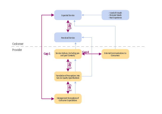
"Dimensions of service quality.
A customer's expectation of a particular service is determined by factors such as recommendations, personal needs and past experiences. The expected service and the perceived service sometimes may not be equal, thus leaving a gap. The service quality model or the ‘GAP model’ developed by a group of authors- Parasuraman, Zeithaml and Berry at Texas and North Carolina in 1985 , highlights the main requirements for delivering high service quality. It identifies five ‘gaps’ that cause unsuccessful delivery. Customers generally have a tendency to compare the service they 'experience' with the service they 'expect' . If the experience does not match the expectation , there arises a gap. Ten determinants that may influence the appearance of a gap were described by Parasuraman, Zeithaml and Berry. in the SERVQUAL model: reliability, responsiveness, competence, access, courtesy, communication, credibility, security, understanding the customer and tangibles.
Later, the determinants were reduced to five: tangibles; reliability; responsiveness; service assurance and empathy in the so called RATER model." [Service quality. Wikipedia]
The block diagram example "Gap model of service quality" was created using the ConceptDraw PRO diagramming and vector drawing software extended with the Block Diagrams solution from the area "What is a Diagram" of ConceptDraw Solution Park.
Block diagram
Electrical Symbols — MOSFET

Block Diagram Creator

Electrical Schematic

Electrical Symbols — Logic Gate Diagram

Electrical Drawing Software and Electrical Symbols

- Av Schematic Diagram
- Mechanical Drawing Symbols | Mechanical Engineering ...
- How To Make A Schematic Diagram For A Chemistry Experiment
- Schematic Diagram Symbol For Chemistry
- Flow chart Example. Warehouse Flowchart | Schematic Diagram ...
- Schematic Diagram Of 3 Bedroom House
- IDEF Business Process Diagrams | Block Diagrams | Network ...
- Schematic Diagram Chemistry Experiment
- Block Diagrams | Schematic Diagram Of Functional Organisational ...
- Block Diagrams | ConceptDraw Arrows10 Technology | Draw A ...
- Process Flowchart | UML Block Diagram | Types of Flowcharts ...
- Chemical Engineering Schematic Drawing Program
- A Schematic Diagram Of Tractor
- Draw A Schematic Diagram To Show The Analytical Process In
- Using Schematic Diagram In Production Management
- Schematic Diagram Of Production System Sample
- Mechanical Schematic Drawing
- Physics Diagrams | How To Make A Schematic Diagram In Lab ...
- Block diagram - Types of individual behavior in organization ...
- Block Diagrams | Building Management System Schematic Diagram ...