Tree Network Topology Diagram

Network Diagram Software ISG Network Diagram


Network Topology

E-R Diagrams

Network Topology Graphical Examples

Bus Network Topology

Cisco Network Examples and Templates

Network Glossary Definition

Star Network Topology


How to Create Cisco Network Diagram

Entity Relationship Diagram Software for Mac

 Computer Network Diagrams
Computer Network Diagrams solution extends ConceptDraw DIAGRAM software with samples, templates and libraries of vector icons and objects of computer network devices and network components to help you create professional-looking Computer Network Diagrams, to plan simple home networks and complex computer network configurations for large buildings, to represent their schemes in a comprehensible graphical view, to document computer networks configurations, to depict the interactions between network's components, the used protocols and topologies, to represent physical and logical network structures, to compare visually different topologies and to depict their combinations, to represent in details the network structure with help of schemes, to study and analyze the network configurations, to communicate effectively to engineers, stakeholders and end-users, to track network working and troubleshoot, if necessary.
Network Community Structure. Computer and Network Examples

Cause and Effect Fishbone Diagram

Electrical Symbols — Transformers and Windings

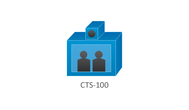
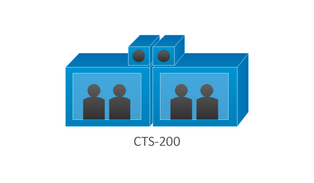
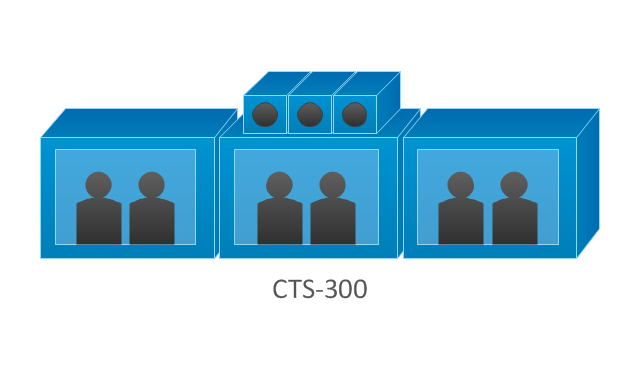
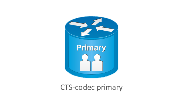
The vector stencils library "Cisco telepresence" contains 8 symbols of videoconference and telepresence equipment for drawing Cisco computer network diagrams.
"Videoconferencing is the conduct of a videoconference (also known as a video conference or videoteleconference) by a set of telecommunication technologies which allow two or more locations to communicate by simultaneous two-way video and audio transmissions. It has also been called 'visual collaboration' and is a type of groupware. ...
The core technology used in a videoconferencing system is digital compression of audio and video streams in real time. The hardware or software that performs compression is called a codec (coder/ decoder). Compression rates of up to 1:500 can be achieved. The resulting digital stream of 1s and 0s is subdivided into labeled packets, which are then transmitted through a digital network of some kind (usually ISDN or IP). The use of audio modems in the transmission line allow for the use of POTS, or the Plain Old Telephone System, in some low-speed applications, such as videotelephony, because they convert the digital pulses to/ from analog waves in the audio spectrum range.
The other components required for a videoconferencing system include:
(1) Video input : video camera or webcam.
(2) Video output: computer monitor, television or projector.
(3) Audio input: microphones, CD/ DVD player, cassette player, or any other source of PreAmp audio outlet.
(4) Audio output: usually loudspeakers associated with the display device or telephone.
(5) Data transfer: analog or digital telephone network, LAN or Internet.
(6) Computer: a data processing unit that ties together the other components, does the compressing and decompressing, and initiates and maintains the data linkage via the network." [Videoconferencing. Wikipedia]
The symbols example "Cisco telepresence - Vector stencils library" was created using the ConceptDraw PRO diagramming and vector drawing software extended with the Cisco Network Diagrams solution from the Computer and Networks area of ConceptDraw Solution Park.
www.conceptdraw.com/ solution-park/ computer-networks-cisco
CTS-100
CTS-200
CTS-300
CTS-codec primary
CTS-codec secondary
TP MCU
Cisco telepresence manager
MCU
Cisco Products Additional. Cisco icons, shapes, stencils and symbols

Azure Management

Network Security Tips

UML Deployment Diagram. Diagramming Software for Design UML Diagrams


- Real Time Example For Meshtopology
- Example Of Mesh Topology In Real Life
- Real Life Example Of Mesh Topology
- Mesh Topology Realtime Example
- Real Time Example For Network Topology
- Real Life Example Of Star Topology
- Real Time Example Of Mesh Topology
- Real Life Situation Example Of Mesh Topology
- Real World Example For Mesh And Bus Topology
- What Is The Real Time Example For Bus Topology
- Network Diagram Examples | Real Life Example Where We Use Bus ...
- Real World Example For Mesh And Bus Topology
- Applications Of Network Topology In Real Life
- Real Time Example For Topology
- Bus Network Topology | Bus Topology Real Time Example
- Network Protocols | Real Time Examples For Wan - Conceptdraw.com
- Computer and Networks Area | Real Time Example Of Ring Topology
- Network Diagram Examples | Real Life Examples Of All The ...
- Real Time Application Of Ring Topology
- Cisco Network Templates | Real Life Examples For Hybrid Topology