 Project Diagrams
The Project Diagrams solution extends the ConceptDraw DIAGRAM software functionality with special tools, large set of samples pre-made in ConceptDraw DIAGRAM and ConceptDraw MINDMAP, and collection of predesigned vector shapes, arrows, table and frame objects for easy drawing the Project Diagrams of different kinds, Hierarchical Charts, Influence Diagrams, Work Breakdown Structures (WBS), Organization Breakdown Structures (OBS), and Resource Breakdown Structures (RBS), PERT Chart or PERT Diagram, Project Management Chart, Project Network Diagram, Network Diagram Project Management, Project Timeline, Precedence Diagram, Gantt Diagram or Gantt Chart. Plan your project, visualize the main stages, and track your project’s implementation effectively with ConceptDraw DIAGRAM. Use also ability to autogenerate Project Diagrams from ConceptDraw MINDMAP to ConceptDraw DIAGRAM.
 Project Management Package
Project Management Package includes a large set of graphical solutions from the ConceptDraw Solution Park. They are selected specially to help in completing the business and management goals, creating business models and modeling business processes, analyzing business progress and efficiency of projects implementation. The tools of this package's solutions are helpful to create number of diagrams and dashboards including Management Diagrams, Business diagrams, Bubble diagrams, Circle-spoke diagrams, Circular arrows diagrams, Venn diagrams, Scrum charts, Kanban boards, Business Intelligence maps, Business Metric charts, Dynamic charts, Project diagrams, Hierarchical charts, Influence diagrams, Work Breakdown Structures (WBS), Resource Breakdown Structures (RBS), PERT Diagrams, Project management charts, Project timelines, Gantt Charts, Funnel diagrams, Stakeholder Onion diagrams, and many more.
Examples of Flowcharts, Org Charts and More


Activity Network Diagram Method

Software Diagram Templates

ConceptDraw PROJECT Project Management Software Tool

 Timeline Diagrams
Timeline Diagrams solution extends ConceptDraw DIAGRAM diagramming software with samples, templates and libraries of specially developed smart vector design elements of timeline bars, time intervals, milestones, events, today marker, legend, and many other elements with custom properties, helpful for professional drawing clear and intuitive Timeline Diagrams. Use it to design simple Timeline Diagrams and designate only the main project stages, or highly detailed Timeline Diagrams depicting all project tasks, subtasks, milestones, deadlines, responsible persons and other description information, ideal for applying in presentations, reports, education materials, and other documentation.
ConceptDraw DIAGRAM Network Diagram Tool


Produce Professional Diagrams More Quickly, Easily and Cost Effectively

Cisco Media. Cisco icons, shapes, stencils and symbols

One formula of professional mind mapping : input data + output data + make great presentation

Affinity Diagram Software

Table Seating Chart Template

PERT Chart Software

UML Use Case Diagram Example. Social Networking Sites Project

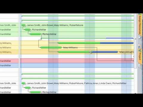
Project — Assigning Resources

Flowchart Programming Project. Flowchart Examples

 Network Layout Floor Plans
Network Layout Floor Plans solution extends ConceptDraw DIAGRAM software functionality with powerful tools for quick and efficient documentation the network equipment and displaying its location on the professionally designed Network Layout Floor Plans. Never before creation of Network Layout Floor Plans, Network Communication Plans, Network Topologies Plans and Network Topology Maps was not so easy, convenient and fast as with predesigned templates, samples, examples and comprehensive set of vector design elements included to the Network Layout Floor Plans solution. All listed types of plans will be a good support for the future correct cabling and installation of network equipment.
Wireless Network LAN

Construction Project Chart Examples

- Draw Network Diagram based on Templates and Examples ...
- Draw Network Diagram based on Templates and Examples ...
- Draw Network Diagram based on Templates and Examples ...
- Network Diagram Software Logical Network Diagram | Network ...
- Examples Of Network Diagrams Project Management
- UML Use Case Diagram Example . Social Networking Sites Project ...
- How To Create a MS Visio Computer Network Diagram Using ...
- Active Directory Domain Services | Active Directory Diagrams
- PERT chart - Template | Cisco Network Diagrams | Computer ...
- How To Create a MS Visio Computer Network Diagram Using ...