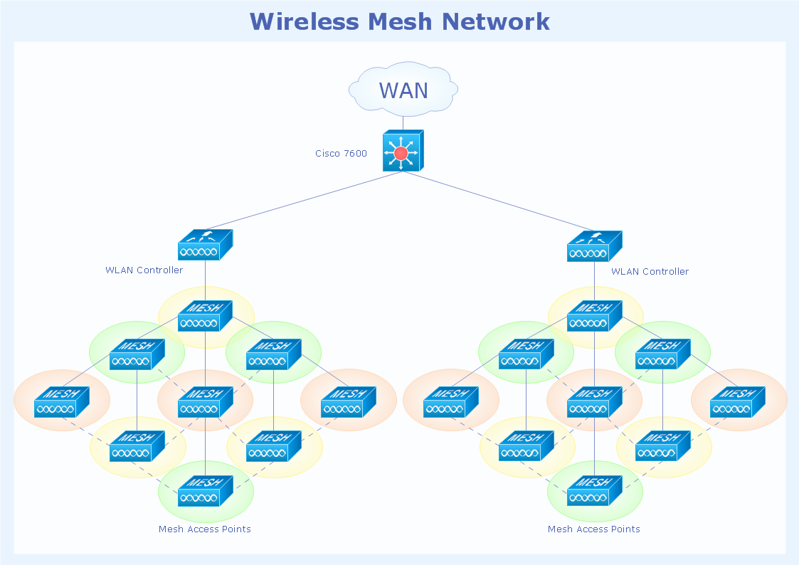
Pic. 1. Wireless mesh network topology diagram.
This Cisco network topology diagram sample is created using ConceptDraw DIAGRAM diagramming and vector drawing software enhanced with Cisco Network Diagrams solution from ConceptDraw Solution Park.

Pic. 2. Cisco Network Topology solution in ConceptDraw STORE
Cisco Network Diagrams solution also provides libraries of Cisco symbols for network components and points, LAN and WAN, schematic and wiring drawings.
Use ConceptDraw DIAGRAM program with of Cisco Network Diagrams solution as tool to draw professional-looking Cisco network architecture, topology, and design diagrams quickly and easily, and to clearly present and communicate it to IT and telecom engineers, designers, stakeholders and end-users.
TEN RELATED HOW TO's:
All networks are different and require a different wiring. They can be simple and consist of two computers connected with a network cable, or complex and consist of several computers, switches, hubs.
This example was created in ConceptDraw DIAGRAM using the Computer and Networks solution from the Computer and Networks area of ConceptDraw Solution Park and shows the Network wiring.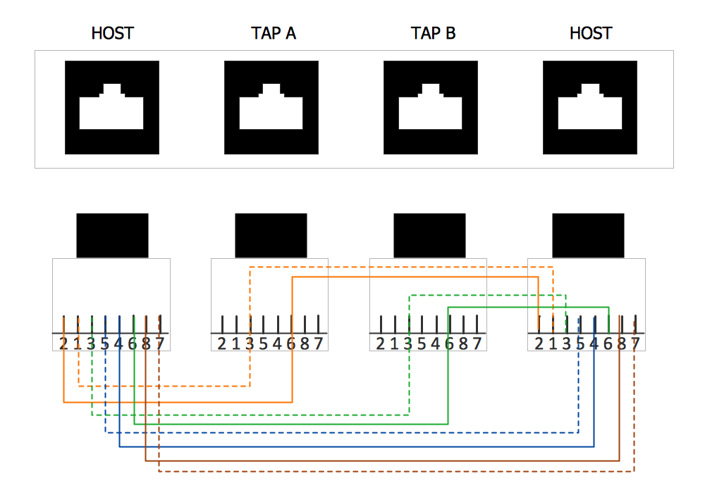
Picture: Network wiring. Computer and Network Examples
Related Solution:
No building project can exist without an electrical circuit map. It’s more convenient to develop electrical drawing with a proper software which would contain vector shapes and electrical symbols. This will help in the future if any problems appear.
This circuit diagram shows the scheme of a location of components and connections of the electrical circuit using a set of standard symbols. It can be use for graphical documentation of an electrical circuit components. There are many of different electric circuit symbols that can be used in a circuit diagram. Knowing how to read circuit diagrams is a useful skill not only for professionals, but for any person who can start creating his own small home electronic projects.
Picture: Electrical Drawing Software and Electrical Symbols
Related Solution:
ConceptDraw Network Diagram is ideal for network engineers and network designers who need to draw Logical Network diagrams.
Picture: Network Diagram SoftwareLogical Network
How to design landscape? You can draw it by hand on a sheet of paper, but for this you need to know the bases of the perspective, you need to have good artistic abilities and to know how to depict the natural elements. But it is much easier and convenient to use the modern ConceptDraw DIAGRAM diagramming and vector drawing software extended with Landscape & Garden Solution from the Building Plans Area.
Picture: How to Design Landscape
Related Solution:
ConceptDraw DIAGRAM is perfect for software designers and software developers who need to draw Rack Diagrams..png)
Picture: Design Element: Rack Diagramfor Network Diagrams
Variable delay elements are often used to manipulate the rising or falling edges of the clock or any other signal in integrated circuits. Delay elements are also used in delay locked loops and in defining a time reference for the movement of data within those systems.
26 libraries of the Electrical Engineering Solution of ConceptDraw DIAGRAM make your electrical diagramming simple, efficient, and effective. You can simply and quickly drop the ready-to-use objects from libraries into your document to create the electrical diagram.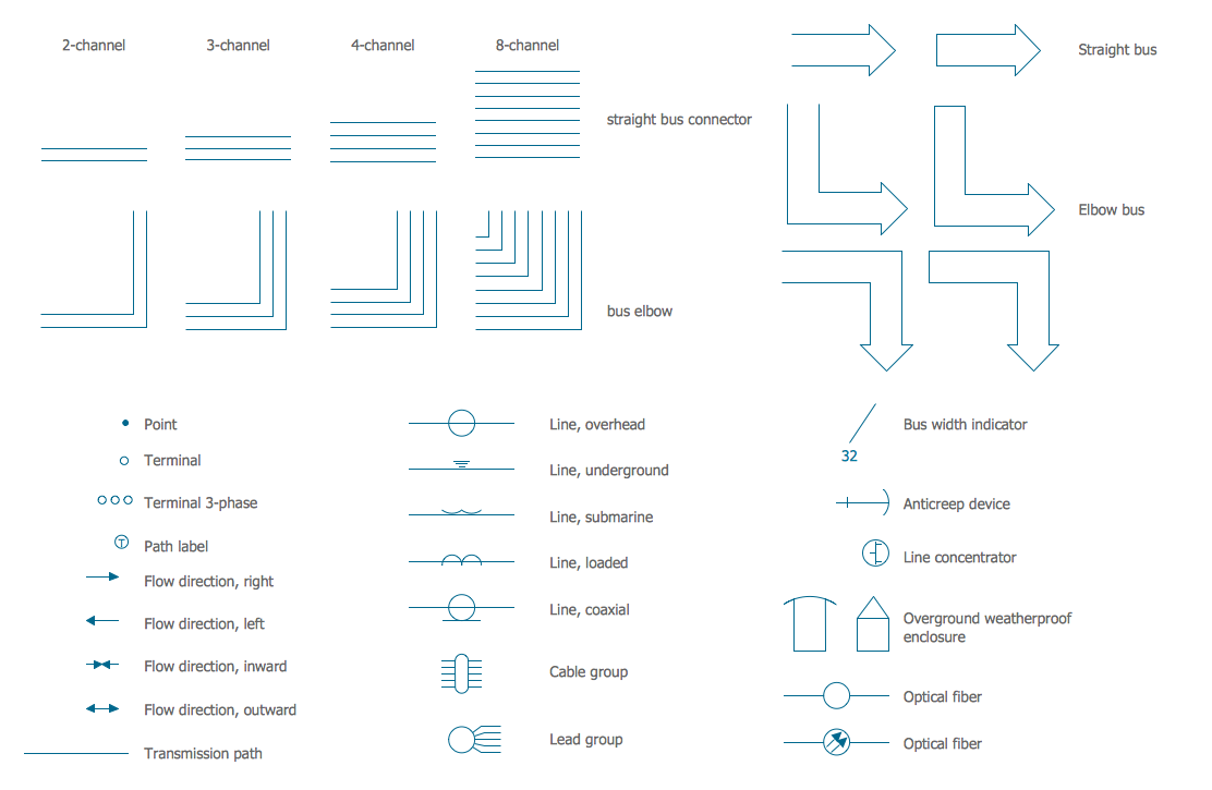
Picture: Electrical Symbols — Transmission Paths
Related Solution:
The Internet Connectivity of the computers, mobile devices, computer networks to the Internet enables the users to access the various Internet services. There are many ways and technologies of the connection to the Internet with different data signaling rates: Wireless, Ethernet cable, Optical fiber, Dial-up, DSL, broadband Internet access, etc.
This example was created in ConceptDraw DIAGRAM using the Computer and Networks solution from the Computer and Networks area of ConceptDraw Solution Park and shows how the customers connect to ISPs and ISPs connect between the tiers (peering and transit).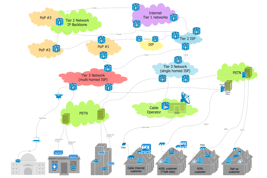
Picture: Internet Connectivity. Computer and Network Examples
Related Solution:
ConceptDraw DIAGRAM is perfect for software designers and software developers who need to draw Network Layout Diagrams._Win_Mac.png)
Picture: Network Diagramming Software for Design Network Layout Diagrams
Related Solution:
The Microsoft Windows Azure platform is a highly flexible cloud-based solution with variety of services which supports not only the execution of.NET applications, but also allows developers to use programming languages like Java, PHP, Node.js, or Python.
ConceptDraw DIAGRAM diagramming and vector drawing software provides the Azure Architecture Solution from the Computer and Networks area of ConceptDraw Solution Park with a lot of useful tools which make easier: illustration of Windows Azure possibilities and features, describing Windows Azure Architecture, drawing Azure Architecture Diagrams, depicting Azure Cloud System Architecture, describing Azure management, Azure storage, documenting Azure services.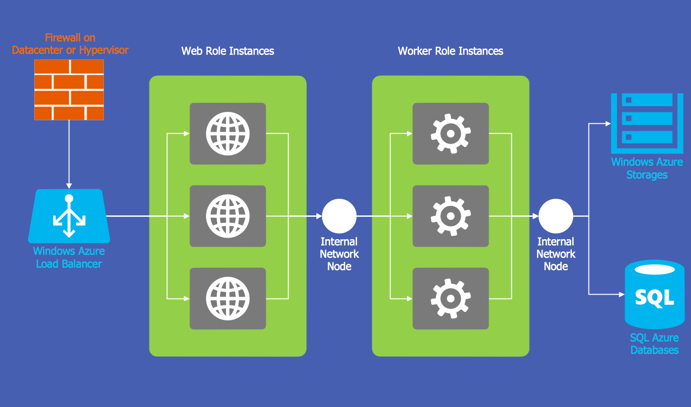
Picture: Windows Azure
Related Solution:
Computer and Networks solution provides the libraries with large quantity of predesigned vector objects and the great number of templates and samples that will help design the Cable Networks in a few minutes.
Picture: Cable Network. Computer and Network Examples
Related Solution:
